Nissan Maxima Service and Repair Manual: Disk eject signal circuit
Description
The eject signal is output to AV control unit when the eject switch of A/C and AV switch assembly is pressed.
Diagnosis Procedure
1.CHECK CONTINUITY DISK EJECT SIGNAL CIRCUIT
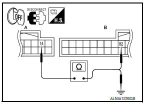
- Turn ignition switch OFF.
- Disconnect A/C and AV switch assembly connector M98 and AV control unit connector M164.
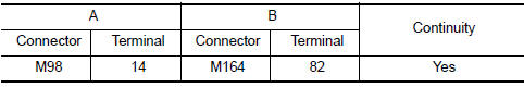
- Check continuity between A/C and AV switch assembly connector M98 (A) terminal 14 and AV control unit harness connector M164 (B) terminal 82.
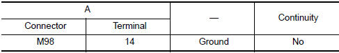
- Check continuity between A/C and AV switch assembly connector M98 (A) terminal 14 and ground.
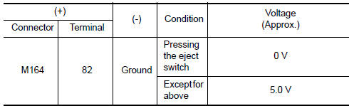
2.CHECK AV CONTROL UNIT VOLTAGE
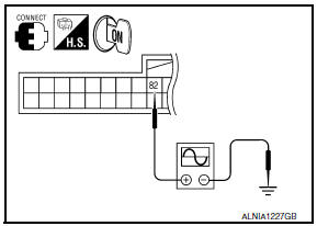
- Connect A/C and AV switch assembly connector M98 and AV control unit connector M164.
- Turn ignition switch ON.
- Check voltage between AV control unit harness connector M164 terminal 82 and ground.
 Aux image signal circuit
Description
Transmits the image signal of AUX device from auxiliary input jacks to
AV control unit.
AV control unit transmits the image signal that is input to the
display unit.
Diagnos ...
 Microphone signal circuit
Description
Voice signals are transmitted from the microphone to the AV control unit
using the microphone signal circuits.
Diagnosis Procedure
1.CHECK HARNESS BETWEEN AV CONTROL UNIT AND MICROPHO ...
Other materials:
Trunk lid opener switch
Removal and Installation
REMOVAL
Remove the instrument lower panel LH. Refer to IP-19, "Removal and
Installation".
Release pawls (A), and press trunk lid opener switch (1) front
side to remove from instrument lower panel LH.
INSTALLATION
Installation is in the reverse ...
Subwoofer
Removal and Installation
Subwoofer (LH)
Subwoofer (RH)
Subwoofer screws
Subwoofer connectors
REMOVAL
Remove the rear parcel shelf finisher. Refer to INT-28, "Removal
and Installation".
Remove the subwoofer screws.
Pull out the subwoofer, disconnect the harness con ...
Symptom diagnosis
CHARGING SYSTEM
Symptom Table
Symptom
Reference
Battery discharged
Refer to CHG-2, "Work Flow (With EXP-800 NI or GR8-1200
NI)"
or CHG-5, "Work Flow (Without EXP-800 NI or GR8-1200 NI)".
The charge warning lamp does not illuminate ...
Nissan Maxima Owners Manual
- Illustrated table of contents
- Safety-Seats, seat belts and supplemental restraint system
- Instruments and controls
- Pre-driving checks and adjustments
- Monitor, climate, audio, phone and voice recognition systems
- Starting and driving
- In case of emergency
- Appearance and care
- Do-it-yourself
- Maintenance and schedules
- Technical and consumer information
Nissan Maxima Service and Repair Manual

0.006