Nissan Maxima Service and Repair Manual: Aux image signal circuit
Description
- Transmits the image signal of AUX device from auxiliary input jacks to AV control unit.
- AV control unit transmits the image signal that is input to the display unit.
Diagnosis Procedure
1.CHECK CONTINUITY AUX IMAGE SIGNAL CIRCUIT
- Turn ignition switch OFF.
- Disconnect auxiliary input jack connector M209 and AV control unit connector M164.
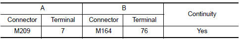
- Check continuity between auxiliary input jack harness connector M209 (A) terminal 7 and AV control unit harness connector M164 (B) terminal 76
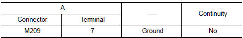
- Check continuity between auxiliary input jack harness connector M209 (A) terminal 8 and ground.
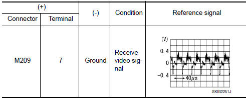
2.CHECK AUX IMAGE SIGNAL
- Connect auxiliary input jack connector M209 and AV control unit connector M164.
- Turn ignition switch ON.
- Check signal between auxiliary input jack connector M209 terminal 7 and ground.
 Composite image signal circuit
Description
AV control unit transmits the playback DVD image signal and AUX image signal
to the display unit.
Diagnosis Procedure
1.CHECK CONTINUITY COMPOSITE IMAGE SIGNAL CIRCUIT
Turn ig ...
 Disk eject signal circuit
Description
The eject signal is output to AV control unit when the eject switch of A/C
and AV switch assembly is pressed.
Diagnosis Procedure
1.CHECK CONTINUITY DISK EJECT SIGNAL CIRCUIT
...
Other materials:
Power supply and ground circuit
Diagnosis Procedure
1.CHECK GROUND CONNECTION-I
Turn ignition switch OFF.
Check ground connection E9. Refer to Ground Inspection
2.CHECK ECM GROUND CIRCUIT FOR OPEN AND SHORT-I
Disconnect ECM harness connector.
Check the continuity between ECM harness connector and ground.
Also che ...
P0300, P0301, P0302, P0303, P0304, P0305, P0306 misfire
DTC Logic
DTC DETECTION LOGIC
When a misfire occurs, engine speed will fluctuate. If the engine speed
fluctuates enough to cause the crankshaft
position (CKP) sensor (POS) signal to vary, ECM can determine that a misfire is
occurring.
The misfire detection logic consists of the followin ...
Fuel injector
Description
The fuel injector is a small, precise solenoid valve. When the ECM
supplies a ground to the fuel injector circuit, the coil in the fuel injector
is energized. The energized coil pulls the ball valve back and
allows fuel to flow via the fuel injector into the intake manifold. T ...
Nissan Maxima Owners Manual
- Illustrated table of contents
- Safety-Seats, seat belts and supplemental restraint system
- Instruments and controls
- Pre-driving checks and adjustments
- Monitor, climate, audio, phone and voice recognition systems
- Starting and driving
- In case of emergency
- Appearance and care
- Do-it-yourself
- Maintenance and schedules
- Technical and consumer information
Nissan Maxima Service and Repair Manual

0.0069