Nissan Maxima Service and Repair Manual: B2608 starter relay
Description
Located in IPDM E/R, it runs the starter motor. The starter relay is turned ON by the BCM when the ignition switch is in START position. IPDM E/R transmits the starter relay ON signal to BCM via CAN communication.
DTC Logic
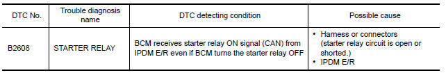
DTC DETECTION LOGIC
NOTE:
-
If DTC B2608 is displayed with DTC U1000, first perform the trouble diagnosis for DTC U1000. Refer to SEC-29, "DTC Logic".
-
If DTC B2608 is displayed with DTC U1010, first perform the trouble diagnosis for DTC U1010. Refer to SEC-30, "DTC Logic".
DTC CONFIRMATION PROCEDURE
1.PERFORM DTC CONFIRMATION PROCEDURE
-
Press the push-button ignition switch under the following conditions.
-
CVT selector lever is in the P or N position.
-
Depress the brake pedal.
-
-
Check "Self diagnostic result" with CONSULT.
Diagnosis Procedure
Regarding Wiring Diagram information, refer to SEC-147, "Wiring Diagram" or SEC-128, "Wiring Diagram".
1.CHECK STARTER RELAY
-
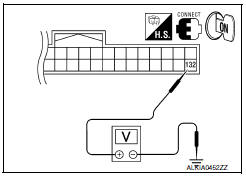
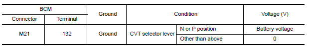
Turn ignition switch ON.
-
Check voltage between BCM harness connector and ground under the following condition.
2.CHECK STARTER RELAY CIRCUIT
-
Turn ignition switch OFF.
-
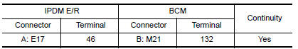
Disconnect BCM harness connector M21 and IPDM E/R harness connector E17.
-
Check continuity between IPDM E/R harness connector E17 (A) terminal 46 and BCM harness connector M21 (B) terminal 132.
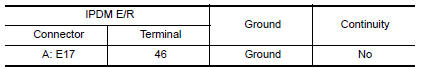
4. Check continuity between IPDM E/R harness connector E17 (A) terminal 46 and ground.
3.CHECK INTERMITTENT INCIDENT
Refer to GI-41, "Intermittent Incident".
Inspection End.
 B2605 transmission range switch
Description
BCM confirms the shift position with the following 4
signals.
CVT selector lever
Transmission range switch
P position signal from IPDM E/R (CAN) ...
 B260f engine status
Description
BCM receives the engine status signal from ECM via CAN
communication.
DTC Logic
DTC DETECTION LOGIC
NOTE:
If DTC B260F is displayed with DTC
U1000, first perform the troubl ...
Other materials:
Timing Chain
Exploded View
Timing chain tensioner (secondary)
Internal chain guide
Timing chain tensioner (secondary)
Camshaft sprocket (EXH)
Timing chain (secondary)
Timing chain (primary)
Camshaft sprocket (INT)
Camshaft sprocket (INT)
Timing chain (secondary)
Camshaft sprocket (E ...
Trunk lamp switch
Description
Detects trunk open/close condition.
Component Function Check
1. CHECK FUNCTION
With CONSULT
Check TRNK/HAT MNTR in Data Monitor mode with CONSULT.
Diagnosis Procedure
1. CHECK TRUNK LAMP SWITCH INPUT SIGNAL
Turn ignit ...
Windows
Power windows
WARNING
Make sure that all passengers have
their hands, etc. inside the vehicle while
it is in motion and before closing the
windows. Use the window lock switch to
prevent unexpected use of the power
windows.
To help avoid risk of injury or death
through unintended o ...
Nissan Maxima Owners Manual
- Illustrated table of contents
- Safety-Seats, seat belts and supplemental restraint system
- Instruments and controls
- Pre-driving checks and adjustments
- Monitor, climate, audio, phone and voice recognition systems
- Starting and driving
- In case of emergency
- Appearance and care
- Do-it-yourself
- Maintenance and schedules
- Technical and consumer information
Nissan Maxima Service and Repair Manual

0.0073