Nissan Maxima Service and Repair Manual: B2605 transmission range switch
Description
BCM confirms the shift position with the following 4 signals.
-
CVT selector lever
-
Transmission range switch
-
P position signal from IPDM E/R (CAN)
-
P position signal from TCM (CAN)
DTC Logic
DTC DETECTION LOGIC
NOTE:
-
If DTC B2605 is displayed with DTC U1000, first perform the trouble diagnosis for DTC U1000. Refer to SEC-29, "DTC Logic".
-
If DTC B2605 is displayed with DTC U1010, first perform the trouble diagnosis for DTC U1010. Refer to SEC-30, "DTC Logic".

DTC CONFIRMATION PROCEDURE
1.PERFORM DTC CONFIRMATION PROCEDURE
-
Turn ignition switch ON under the following conditions and wait for at least 1 second.
-
CVT selector lever is in the P or N position
-
Do not depress the brake pedal.
-
-
Check "Self diagnostic result" with CONSULT.
Diagnosis Procedure
Regarding Wiring Diagram information, refer to SEC-147, "Wiring Diagram" or SEC-128, "Wiring Diagram".
1.CHECK DTC WITH IPDM E/R
Check "Self diagnostic result" with CONSULT. Refer to PCS-27, "DTC Index".
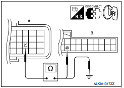
2.CHECK TRANSMISSION RANGE SWITCH CIRCUIT
-
Turn ignition switch OFF.
-
Disconnect TCM harness connector and BCM harness connector.
-
Check continuity between TCM connector F15 (A) terminal 20 and BCM harness connector M18 (B) terminal 48.


4. Check continuity between TCM harness connector F15 (A) terminal 20 and ground.

3.CHECK INTERMITTENT INCIDENT
Refer to GI-41, "Intermittent Incident".
Inspection End.
 B2604 transmission range switch
Description
BCM confirms the shift position with the following 4
signals.
CVT selector lever
Transmission range switch
P position signal from IPDM E/R (CAN) ...
 B2608 starter relay
Description
Located in IPDM E/R, it runs the starter motor. The
starter relay is turned ON by the BCM when the ignition
switch is in START position. IPDM E/R transmits the starter relay ON signal ...
Other materials:
Unit removal and installation
Rear suspension assembly
Exploded View
Rear shock absorber cap
Strut mount insulator
Shock absorber mount seal
Rear suspension bound bumper
Rear shock absorber
Rear suspension arm
Connecting rod mount bracket
Rear stabilizer connecting rod
Rear spring upper rubber seat ...
B1113 - B1115 satellite sensor RH
Description
DTC B1113 - B1115 SATELLITE SENSOR RH
The satellite sensor RH is wired to the air bag diagnosis sensor unit. The
air bag diagnosis sensor unit willmonitor the satellite sensor RH for
internal failures and its circuits for communication errors.
PART LOCATION
DTC Logic
DTC DETECTI ...
Headlamp (LO) circuit
Description
The IPDM E/R (intelligent power distribution module engine room) controls the
headlamp low relay based on inputs from the BCM over the CAN communication
lines. When the headlamp low relay is energized, power flows through fuses 51
and 52, located in the IPDM E/R. Power then flows ...
Nissan Maxima Owners Manual
- Illustrated table of contents
- Safety-Seats, seat belts and supplemental restraint system
- Instruments and controls
- Pre-driving checks and adjustments
- Monitor, climate, audio, phone and voice recognition systems
- Starting and driving
- In case of emergency
- Appearance and care
- Do-it-yourself
- Maintenance and schedules
- Technical and consumer information
Nissan Maxima Service and Repair Manual
0.0074
