Nissan Maxima Service and Repair Manual: Air mix door control system
System Diagram
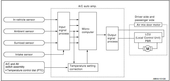
System Description
The air mix doors are automatically controlled so that in-vehicle temperature is maintained at a predetermined value by the temperature setting, ambient temperature, intake temperature and amount of sunload.
SYSTEM OPERATION
- The A/C auto amp. receives data from each of the sensors.
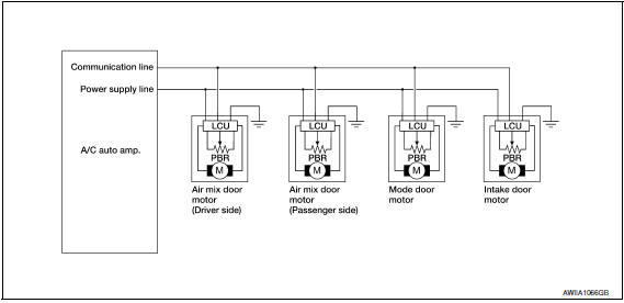
- The A/C auto amp. sends air mix door, the mode door and the intake door opening angle data to the air mix door motor LCU(s), the mode door motor LCU and the intake door motor LCU.
- The air mix door motor(s), the mode door motor and the intake door motor read their respective signals according to the address signal. Opening angle indication signals received from the A/C auto amp. and each of the motor position sensors are compared by the LCUs in each door motor with the existing decision and opening angles.
- Next, HOT/COLD, DEF/VENT or FRE/REC operation is selected. The newly selected data is returned to the A/C auto amp.
Door Motor Circuit
Air Mix Door Control Specification
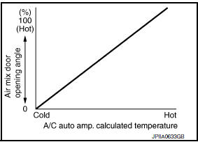
When ignition switch is ON, the A/C auto amp. continuously and automatically controls temperatures, regardless of air conditioner operational condition. When setting a target temperature with the temperature control switch, the A/C auto amp. corrects the set temperature and decides a target air mix door opening angle. The A/C auto amp. controls the air mix door according, to the target air mix door opening angle and the current air mix door opening angle, keeping an optimum air mix door opening angle. When the temperature is set at 18C (60F), air mix door is set on full-cold, and when the temperature is set at 32C (90F), it is set to full-hot.
 Mode door control system
System Diagram
System Description
The mode door is automatically controlled by the temperature setting, ambient
temperature, in-vehicle temperature,
intake temperature and amount of sunload.
...
 Intake door control system
System Diagram
System Description
The intake doors are automatically controlled by the temperature setting,
ambient temperature, in-vehicle temperature,
intake temperature, amount of sunload ...
Other materials:
C1120, C1122, C1124, C1126 in ABS sol
Description
The solenoid valve increases, holds or decreases the fluid pressure of each
brake caliper according to the signals
transmitted by the ABS actuator and electric unit (control unit).
DTC Logic
DTC DETECTION LOGIC
DTC CONFIRMATION PROCED ...
Intelligent key battery
Removal and Installation
Release the lock knob at the back of the Intelligent Key and remove the
mechanical key.
Insert a suitable tool (A) wrapped with a cloth into the slit of the
corner and twist it to separate the upper part from the lower part.
Replace the battery with new o ...
Precaution
Precaution for Supplemental Restraint System (SRS) "AIR BAG" and
"SEAT BELT PRE-TENSIONER"
The Supplemental Restraint System such as "AIR BAG" and "SEAT BELT
PRE-TENSIONER", used along with a front seat belt, helps to reduce the risk
or severity of injury to the driver and front passenger for ...
Nissan Maxima Owners Manual
- Illustrated table of contents
- Safety-Seats, seat belts and supplemental restraint system
- Instruments and controls
- Pre-driving checks and adjustments
- Monitor, climate, audio, phone and voice recognition systems
- Starting and driving
- In case of emergency
- Appearance and care
- Do-it-yourself
- Maintenance and schedules
- Technical and consumer information
Nissan Maxima Service and Repair Manual

0.0056