Nissan Maxima Service and Repair Manual: Intake door control system
System Diagram
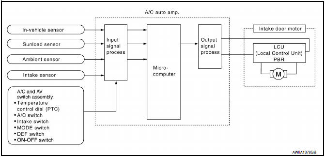
System Description
The intake doors are automatically controlled by the temperature setting, ambient temperature, in-vehicle temperature, intake temperature, amount of sunload and ON/OFF operation of the compressor.
SYSTEM OPERATION
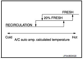
The intake door control judges intake door position based on the ambient temperature, the intake air temperature and the in-vehicle temperature. When in shifting mode position D/F, if the DEF or OFF switches are pressed, or when the A/C switch is OFF, the A/C auto amp. sets the intake door to the FRE position.
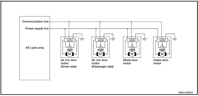
Door Motor Circuit
Intake Door Control Specification
 Air mix door control system
System Diagram
System Description
The air mix doors are automatically controlled so that in-vehicle temperature
is maintained at a predetermined
value by the temperature setting, ambient temp ...
 Blower motor control system
System Diagram
System Description
Fan speed is automatically controlled by the temperature setting, ambient
temperature, in-vehicle temperature,
intake temperature, amount of sunload and air ...
Other materials:
System maintenance
The sensor for the ICC system A is located on
the front of the vehicle.
To keep the ICC system operating properly, be
sure to observe the following:
Always keep the sensor area clean.
Do not strike or damage the areas around
the sensor. Do not touch or remove the
screw located on ...
U1200 AV control unit
Description
Replace the AV control unit if this DTC is displayed.
Part name
Description
AV CONTROL UNIT
It is the master unit of the MULTI AV system and it is connected
to each control unit by means of communication. It operates each
syste ...
Seat belt warning light
Both the driver's and passenger's front seats are
equipped with a seat belt warning light. The
warning light, located on the instrument panel,
will show the status of the driver and passenger
seat belt.
NOTE:
The front passenger seat belt warning light
will not light up if the seat is not ...
Nissan Maxima Owners Manual
- Illustrated table of contents
- Safety-Seats, seat belts and supplemental restraint system
- Instruments and controls
- Pre-driving checks and adjustments
- Monitor, climate, audio, phone and voice recognition systems
- Starting and driving
- In case of emergency
- Appearance and care
- Do-it-yourself
- Maintenance and schedules
- Technical and consumer information
Nissan Maxima Service and Repair Manual

0.0073