Nissan Maxima Service and Repair Manual: Automatic air conditioner system
System Diagram
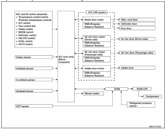
CONTROL SYSTEM
The control system consists of input sensors, switches, the A/C auto amp. (microcomputer) and outputs. The relationship of these components is as shown in the figure below:
System Description
CONTROL OPERATION
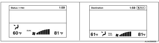
Display
The operation status of the HVAC system is displayed on the screen.
A/C and AV Switch Assembly
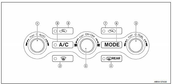
- Temperature control dial (driver side)/AUTO switch
- Defroster switch
- ON - OFF switch/fan control dial
- Rear window defogger switch
- Temperature control dial (passenger)/ DUAL mode switch
- Mode switch
- Fresh air switch
- Recirculation switch
- A/C ON/OFF switch
MODE SWITCH
The air discharge outlets are controlled with this switch.
TEMPERATURE CONTROL DIAL (Driver Side)
The set temperature is increased or decreased with this dial.
TEMPERATURE CONTROL DIAL (Passenger Side)
- The set temperature is increased or decreased with this dial.
- When the temperature control dial is turned, DUAL switch indicator is turned ON.
AUTO SWITCH
- The compressor, intake doors, air mix doors, mode doors and blower speed are automatically controlled so that the in-vehicle temperature will reach, and be maintained at the set temperature selected by the operator.
- When pressing the AUTO switch, air inlet, air outlet, fan speed, and discharge air temperature are automatically controlled.
DEFROSTER ( ) SWITCH
Mode doors are set to the defrost position with this switch. Also, intake doors are set to the outside air position, and compressor turns ON.
A/C SWITCH
Compressor turns ON or OFF with this switch.
(Pressing the A/C switch when the A/C switch is ON turns OFF the A/C switch and compressor.)
FAN CONTROL DIAL
The fan speed is manually controlled with this dial. Seven speeds are available for manual control (as shown on the display screen).
ON - OFF SWITCH
Compressor and blower turn OFF, intake doors and the mode doors are automatically controlled.
REAR WINDOW DEFOGGER SWITCH
When indicator is ON, rear window is defogged.
RECIRCULATION (  ) SWITCH
- When the REC switch is ON, the REC switch indicator is turned ON, and air inlet is set to REC.
FRESH AIR (  ) SWITCH
- When the FRE switch is ON, the FRE switch indicator is turned ON, and air inlet is set to FRE
DUAL MODE SWITCH
- When the DUAL switch indicator is ON, the driver side and passenger side, temperature can each be set independently.
- When the DUAL switch indicator is OFF, the driver side outlet and setting temperature are applied to both sides.
Air Conditioner LAN Control System
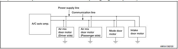
The LAN (Local Area Network) system consists of the A/C auto amp., the mode door motor, the air mix door motors and the intake door motor.
A configuration of these components is as shown in the figure below.
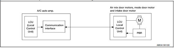
SYSTEM CONSTRUCTION
A small network exists between the A/C auto amp., the mode door motor, the air mix door motors and the intake door motor. The A/C auto amp. and motors are connected by data transmission lines and motor power supply lines. The LAN network is built through the ground circuits of each door motor.
Addresses, motor opening angle signals, motor stop signals and error checking messages are all transmitted through the data transmission lines connecting the A/C auto amp. and each door motor.
The following functions are contained in LCUs built into the mode door motor, the air mix door motors and the intake door motor.
- Address
- Motor opening angle signals
- Data transmission
- Motor stop and drive decision
- Opening angle sensor (PBR function)
- Comparison
- Decision (A/C auto amp. indicated value and motor opening angle comparison)
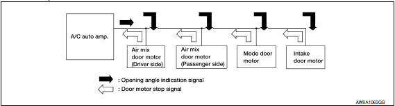
Operation
The A/C auto amp. receives data from each of the sensors. The A/C auto amp. sends mode door, the air mix door and the intake door opening angle data to the mode door motor LCU, the air mix door motor LCUs and the intake door motor LCU.
The mode door motor, the air mix door motors and the intake door motor read their respective signals according to the address signal. Opening angle indication signals received from the A/C auto amp. and each of the motor position sensors is compared by the LCUs in each door motor with the existing decision and opening angles. Next, HOT/COLD, DEF/VENT or FRE/REC operation is selected. The new selection data is returned to the A/C auto amp.
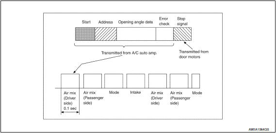
Transmission Data and Transmission Order
A/C auto amp. data is transmitted consecutively to each of the door motors following the form as shown in the figure below.
START:
- Initial compulsory signal is sent to each of the door motors.
ADDRESS:
- Data sent from the A/C auto amp. is selected according to data-based decisions made by the mode door motor, the air mix door motors and the intake door motor.
- If the addresses are identical, the opening angle data and error check signals are received by the door motor LCUs. The LCUs then make the appropriate error decision. If the opening angle data has no error, door control begins.
- If an error exists, the received data is rejected and the corrected data received. Finally, door control is based upon the corrected opening angle data.
OPENING ANGLE:
- Data that shows the indicated door opening angle of each door motor.
ERROR CHECK:
- In this procedure, transmitted and received data is checked for errors. Error data is then compiled. The error check prevents corrupted data from being used by the mode door motor, the air mix door motors and the intake door motor. Error data can be related to the following symptoms:
- Malfunction of electrical frequency
- Poor electrical connections
- Signal leakage from transmission lines
- Signal level fluctuation
STOP SIGNAL:
- At the end of each transmission, a stop operation, in-operation, or internal malfunction message is delivered to the A/C auto amp. This completes one data transmission and control cycle.
AIR MIX DOOR CONTROL (AUTOMATIC TEMPERATURE CONTROL)
- The air mix doors are automatically controlled so that in-vehicle temperature is maintained at a predetermined value by the temperature setting, ambient temperature, in-vehicle temperature and amount of sunload.
FAN SPEED CONTROL
- Fan speed is automatically controlled by the temperature setting,
ambient temperature, in-vehicle temperature,
intake temperature, amount of sunload and air mix door position.
With pressing AUTO switch, the blower motor starts to gradually increase airflow volume.
When engine coolant temperature is low, the blower motor operation is delayed to prevent cool air from flowing.
INTAKE DOOR CONTROL
- The intake doors are automatically controlled by the temperature setting, ambient temperature, in-vehicle temperature, intake temperature, amount of sunload and ON/OFF operation of the compressor.
MODE DOOR CONTROL
- The mode door is automatically controlled by the temperature setting, ambient temperature, in-vehicle temperature, intake temperature and amount of sunload.
MAGNET CLUTCH CONTROL
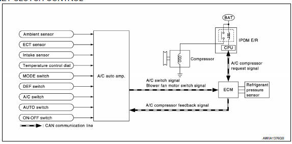
When A/C switch, AUTO switch or DEF ( ) switch is pressed, A/C auto amp. transmits compressor ON signal
to ECM, via CAN communication.
) switch is pressed, A/C auto amp. transmits compressor ON signal
to ECM, via CAN communication.
ECM judges whether compressor can be turned ON, based on each sensor status (refrigerant pressure sensor signal, throttle angle, etc.). If it judges compressor can be turned ON, it sends compressor ON signal to IPDM E/R, via CAN communication.
Upon receipt of compressor ON signal from ECM, IPDM E/R turns air conditioner relay ON to operate compressor.
When sending compressor ON signal to IPDM E/R via CAN communication line, ECM simultaneously sends compressor feedback signal to A/C auto amp. via CAN communication line.
- Mode door control system
- Air mix door control system
- Intake door control system
- Blower motor control system
- Magnet clutch control system
- CAN communication system
- Diagnosis system (HVAC)
 System description
COMPRESSOR CONTROL FUNCTION
Description
PRINCIPLE OF OPERATION
Compressor is not activated.
Functional circuit diagram
CAN (1): A/C switch signal
: Blower fan motor switch signal
CAN (2): A ...
 Mode door control system
System Diagram
System Description
The mode door is automatically controlled by the temperature setting, ambient
temperature, in-vehicle temperature,
intake temperature and amount of sunload.
...
Other materials:
Audio unit
Reference Value
TERMINAL LAYOUT
PHYSICAL VALUES
...
Both doors mirror defogger don't operate but rear window
defogger operates
Diagnosis Procedure
1. CHECK DOOR MIRROR DEFORGGER FUSE
Check if the following fuse in fuse block (J/B) is blown.
2. CHECK DOOR MIRROR DEFORGGER CIRCUIT
Turn ignition switch OFF.
Disconnect the following harness connectors.
Fuse block (J/B) connector M5
Door mirror LH D4
Door ...
Rear door speaker
Description
The audio unit sends audio signals to the BOSE speaker amp. The BOSE speaker
amp. amplifies the audio signals before sending them to the rear door
speakers using the audio signal circuits.
Diagnosis Procedure
1.CONNECTOR CHECK
Check the audio unit, BOSE speaker amp. and speaker c ...
Nissan Maxima Owners Manual
- Illustrated table of contents
- Safety-Seats, seat belts and supplemental restraint system
- Instruments and controls
- Pre-driving checks and adjustments
- Monitor, climate, audio, phone and voice recognition systems
- Starting and driving
- In case of emergency
- Appearance and care
- Do-it-yourself
- Maintenance and schedules
- Technical and consumer information
Nissan Maxima Service and Repair Manual

0.0056