Nissan Maxima Service and Repair Manual: Magnet clutch control system
System Diagram
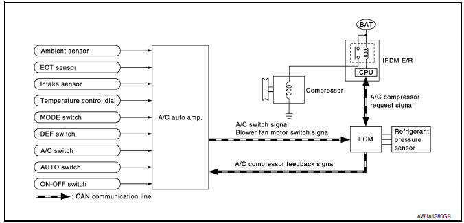
System Description
The A/C auto amp. controls compressor operation by ambient temperature, intake air temperature and signal from ECM.
SYSTEM OPERATION
When the A/C switch, the AUTO switch, or the DEF switch is pressed, or when shifting mode position to D/F, the A/C auto amp. transmits the A/C switch signal and blower fan motor switch signal to the ECM, via CAN communication.
ECM judges whether compressor can be turned ON, based on each sensor status (refrigerant-pressure sensor signal, throttle angle, etc.). If the ECM judges that the compressor can be turned ON, it sends A/C compressor request signal to the IPDM E/R, via CAN communication.
Upon receipt of A/C compressor request signal from the ECM, the IPDM E/R turns the A/C relay ON to operate the compressor.
When sending A/C compressor request signal to the IPDM E/R via CAN communication line, the ECM simultaneously sends A/C compressor feedback signal to A/C auto amp. via CAN communication line.
The ECM sends A/C compressor feedback signal to A/C auto amp., then, uses input A/C compressor feedback signal to control air inlet.
Compressor Protection Control The ECM makes the A/C relay turn OFF and stops the compressor when pressure on the high-pressure side, detected by the refrigerant pressure sensor, is over approximately 3,119 kPa (31.8 kg/cm2, 452 psi), or below approximately 118 kPa (1.2 kg/cm2, 17 psi).
Low Temperature Protection Control Turn the A/C relay to OFF and stop the A/C compressor by the signal from the A/C auto amp., according to the evaporator passing air temperature detected by the intake sensor and the ambient temperature detected by the ambient sensor.
 Blower motor control system
System Diagram
System Description
Fan speed is automatically controlled by the temperature setting, ambient
temperature, in-vehicle temperature,
intake temperature, amount of sunload and air ...
 CAN communication system
System Description
CAN (Controller Area Network) is a serial communication line for real time
application. It is an on-vehicle multiplex
communication line with high data communication speed and e ...
Other materials:
Positive crankcase ventilation
Description
This system returns blow-by gas to the intake manifold.
The positive crankcase ventilation (PCV) valve is provided to conduct crankcase
blow-by gas to the intake
manifold.
During partial throttle operation of the engine, the intake manifold sucks the
blow-by gas via the ...
Fuel pump
Description
*: ECM determines the start signal status by the signals of engine speed and
battery voltage.
The ECM activates the fuel pump for several seconds after the ignition switch is
turned ON to improve engine
start ability. If the ECM receives a engine speed signal from the camsh ...
Headlamp (HI) circuit
Description
The IPDM E/R (intelligent power distribution module engine room) controls the
headlamp high relay based on inputs from the BCM over the CAN communication
lines. When the headlamp high relay is energized, power flows through fuses
48 and 49, located in the IPDM E/R. Power then flow ...
Nissan Maxima Owners Manual
- Illustrated table of contents
- Safety-Seats, seat belts and supplemental restraint system
- Instruments and controls
- Pre-driving checks and adjustments
- Monitor, climate, audio, phone and voice recognition systems
- Starting and driving
- In case of emergency
- Appearance and care
- Do-it-yourself
- Maintenance and schedules
- Technical and consumer information
Nissan Maxima Service and Repair Manual

0.0107