Nissan Maxima Service and Repair Manual: Blower motor control system
System Diagram
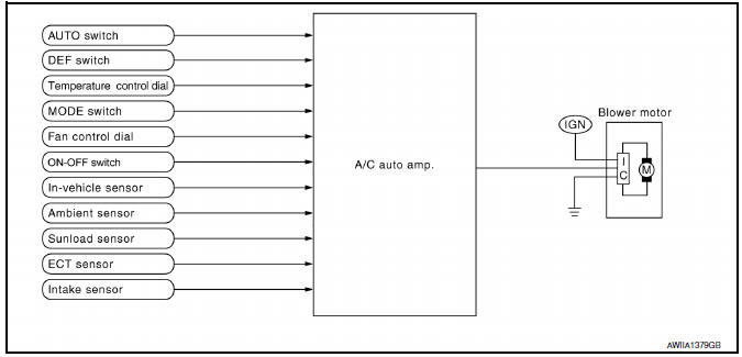
System Description
Fan speed is automatically controlled by the temperature setting, ambient temperature, in-vehicle temperature, intake temperature, amount of sunload and air mix door position.
By pressing the AUTO switch, the blower motor starts to gradually increase airflow volume.
When engine coolant temperature is low, the blower motor operation is delayed to prevent cool air from flowing.
SYSTEM OPERATION
System Operation
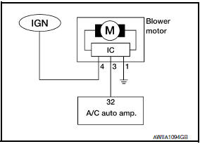
- For airflow, the manual selection (1-7) with the fan control dial has priority.
- If the AUTO switch is pressed or if the DEF switch is pressed while in the OFF condition, it changes to the automatic control by A/C auto amp.
- When increasing the airflow, it changes the duty ratio of the blower motor drive signal to prevent the airflow from suddenly increasing.
- There are the following types of airflow control: starting airflow control, starting airflow control at low coolant temperature, starting airflow control at high in-vehicle temperature, and airflow control at actuator operation in addition to manual control, normal automatic airflow control
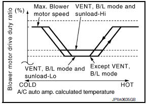
Normal Automatic Airflow Control
- When the target temperature is set by the temperature control dial of A/C and AV switch assembly, the A/C auto amp. performs the calculation and decides the target according to the signal from each sensor.
- The A/C auto amp. changes the duty ratio of blower motor drive signal and controls the airflow, continuously, so that the airflow becomes the target airflow.
- The minimum airflow will change according to the sunload when the air discharge outlet is VENT or B/L.
Fan Speed Control Specification
Starting Airflow Control
- When starting the automatic control of airflow, the system gradually increases the duty ratio of the blower motor drive signal to prevent too much air from blowing.
- The time period from when the airflow changes from LO to HI is approximately 8 seconds.
- It becomes the starting airflow control at low coolant temperature according to the calculation result of the A/ C auto amp. and engine coolant temperature [approximately 56C (133F) or less] during the automatic airflow control.
- Do not perform the starting airflow control when the air discharge outlet is set to DEF.
Starting Fan Speed Control
Start-up from COLD SOAK Condition (Automatic mode) In cold start-up condition where the engine coolant temperature is below 56C (133F), the blower does not operate for a short period of time (up to 150 seconds). The exact start delay time varies depending on the ambient temperature and engine coolant temperature.
In the most extreme case (very low ambient temperature) the blower start delay is 150 seconds, as described above. After this delay, the blower will operate at low speed until the engine coolant temperature rises above 56C (133F), and then the fan speed increases to the objective speed.
Start-up from usual or HOT SOAK Condition (Automatic mode) The blower will begin operation momentarily after the AUTO switch is pressed. The fan speed rises gradually to the objective speed over a time period of 3 seconds or less (actual time depends on the objective fan speed).
 Intake door control system
System Diagram
System Description
The intake doors are automatically controlled by the temperature setting,
ambient temperature, in-vehicle temperature,
intake temperature, amount of sunload ...
 Magnet clutch control system
System Diagram
System Description
The A/C auto amp. controls compressor operation by ambient temperature,
intake air temperature and signal
from ECM.
SYSTEM OPERATION
When the A/C switch, t ...
Other materials:
Front disc brake
Disassembly and Assembly
Union bolt
Copper sealing washer
Brake hose
Cap
Bleed valve
Sliding pin bolt
Piston seal
Piston
Piston boot
Cylinder body
Upper sliding pin
Lower sliding pin bolt
Torque member bolt
Washer
Sliding pin boot
Bushing
Torque memb ...
P0643 sensor power supply
DTC Logic
DTC DETECTION LOGIC
DTC CONFIRMATION PROCEDURE
1.PRECONDITIONING
If DTC Confirmation Procedure has been previously conducted, always perform
the following before conducting
the next test.
Turn ignition switch OFF and wait at least 10 seconds.
Turn ignition switch ON.
Tu ...
System maintenance
The sensor A is located behind the lower grille
of the front bumper.
To keep the system operating properly, be sure to
observe the following:
Always keep the sensor area of the front
bumper clean.
Do not strike or damage the areas around
the sensor.
Do not cover or attach st ...
Nissan Maxima Owners Manual
- Illustrated table of contents
- Safety-Seats, seat belts and supplemental restraint system
- Instruments and controls
- Pre-driving checks and adjustments
- Monitor, climate, audio, phone and voice recognition systems
- Starting and driving
- In case of emergency
- Appearance and care
- Do-it-yourself
- Maintenance and schedules
- Technical and consumer information
Nissan Maxima Service and Repair Manual

0.0069