Nissan Maxima Service and Repair Manual: Paddle shifter
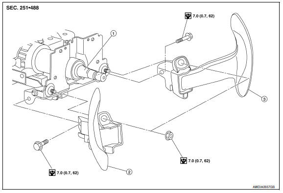
Exploded View
-
Steering column assembly
-
Paddle shifter (shift-down)
-
Paddle shifter (shift-up)
Removal and Installation
REMOVAL
-
Park the vehicle on a level surface.
-
Remove the driver air bag module. Refer to SR-12, "Exploded View".
-
Remove the steering wheel. Refer to ST-17, "Removal and Installation".
-
Remove the column cover. Refer to IP-13, "Removal and Installation".
-
Remove the vehicle harness connector (C) and (D) from paddle shifter.
(A) : Side of paddle shifter (shift-down)
(B) : Side of paddle shifter (shift-up)
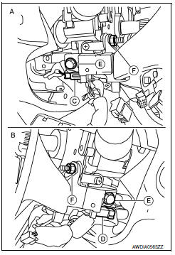
6. Remove the paddle shifter bolts (E) and nuts (F).
7. Remove the paddle shifter from the steering column assembly.
INSTALLATION
Installation is in the reverse order of removal.
 Control cable
Exploded View
CVT shift selector assembly
Control cable
Retainer grommet
Lock plate
Bracket
Transaxle assembly
...
 Oil pan
Exploded View
Transaxle assembly
Oil pan bolt
Drain plug
O-ring
Oil pan
Oil pan gasket
Magnet
...
Other materials:
BCM (body control module)
Reference Value
NOTE:
The Signal Tech II Tool (J-50190) can be used to perform the
following functions. Refer to the Signal Tech II
User Guide for additional information.
Activate and display TPMS transmitter IDs
Display tire pressure reported by the TPMS transmitter
Read TPMS DTCs
R ...
Horn
Description
Horn (high/low) is located inside of front bumper and
operates when theft warning system is in alarm phase.
Component Function Check
1.CHECK FUNCTION
Select HORN in "ACTIVE TEST" mode with CONSULT.
Check the horn (high/low) operation.
Diagnosis Pro ...
Audio antenna
Location of Antenna
AV control unit
AV control unit antenna feeder
In-line connectors M103, M501
Antenna amp.
Window antenna
Satellite radio antenna feeder
Satellite radio antenna
Window Antenna Repair
ELEMENT CHECK
Attach probe circuit tester (ohm setting) to antenna ...
Nissan Maxima Owners Manual
- Illustrated table of contents
- Safety-Seats, seat belts and supplemental restraint system
- Instruments and controls
- Pre-driving checks and adjustments
- Monitor, climate, audio, phone and voice recognition systems
- Starting and driving
- In case of emergency
- Appearance and care
- Do-it-yourself
- Maintenance and schedules
- Technical and consumer information
Nissan Maxima Service and Repair Manual

0.0082