Nissan Maxima Service and Repair Manual: ECU diagnosis information
ABS ACTUATOR AND ELECTRIC UNIT (CONTROL UNIT)
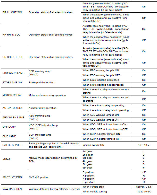
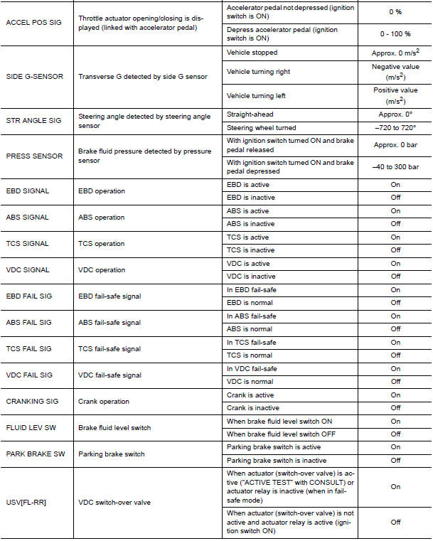
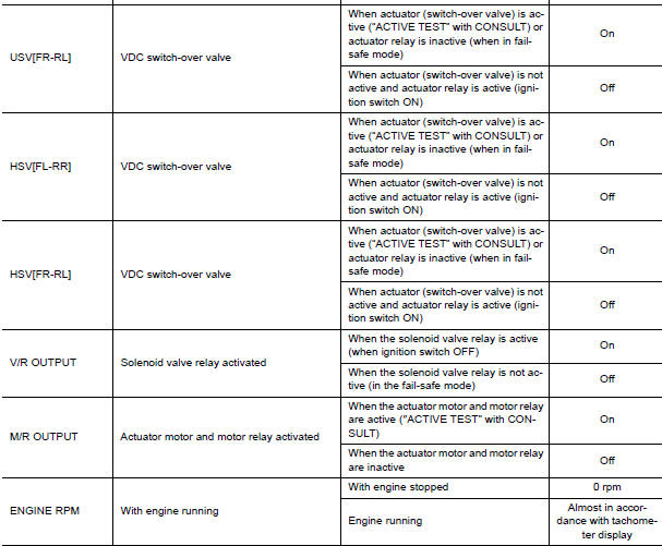
Reference Value
VALUES ON THE DIAGNOSIS TOOL
CAUTION: The display shows the control unit calculation data, so a normal value might be displayed even in the event the output circuit (harness) is open or short-circuited.
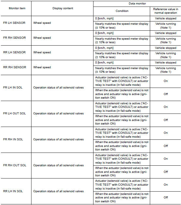
Note 1: Confirm tire pressure is normal.
Note 2: On and off timing for warning lamp and indicator lamp.
Fail-Safe
CAUTION: If the Fail-Safe function is activated, perform self-diagnosis for VDC/TCS/ABS system.
ABS, EBD SYSTEM
In case of an electrical malfunction with the ABS, ABS warning lamp and SLIP indicator lamp will turn on. In case of an electrical malfunction with the EBD system, brake warning lamp, ABS warning lamp and SLIP indicator lamp will turn on. The system will revert to one of the following conditions of the fail-safe function.
- For ABS malfunction, only the EBD is operative and the condition of vehicle is the same condition of vehicles without VDC/TCS/ABS system.
- For EBD malfunction, the EBD and ABS become inoperative, and the condition of vehicle is the same as the condition of vehicles without VDC/TCS/ABS or EBD system.
VDC / TCS
In case of VDC/TCS system malfunction, SLIP indicator lamp is turned on, and the condition of vehicle is the same as the condition of vehicles without VDC/TCS system. In case of an electrical malfunction with the VDC/ TCS system, the ABS control continues to operate normally without VDC/TCS control.
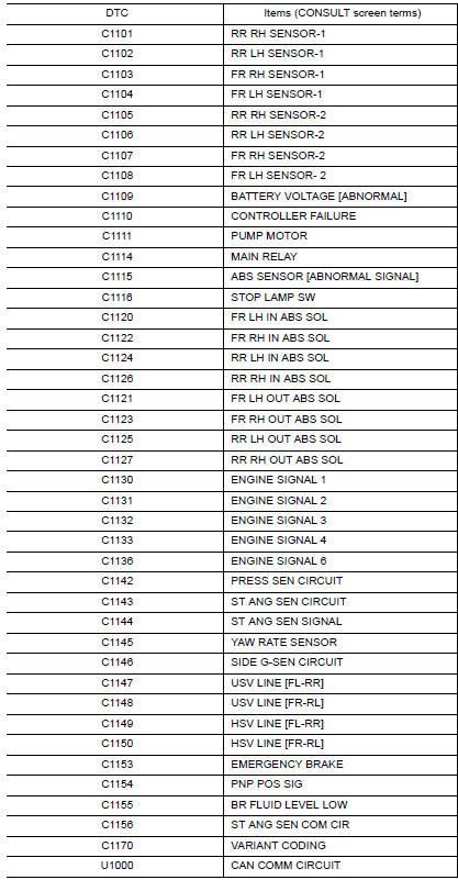
DTC No. Index
 Slip indicator lamp
Description
Component Function Check
1.CHECK SLIP INDICATOR LAMP OPERATION
Check that the lamp illuminates for approximately 2 seconds after the
ignition switch is turned ON.
Diagnosis Proce ...
 Wiring diagram
BRAKE CONTROL SYSTEM
Wiring Diagram
...
Other materials:
Waxing
Regular waxing protects the paint surface and
helps retain new vehicle appearance. Polishing is
recommended to remove built-up wax residue
and to avoid a weathered appearance before
re-applying wax.
A NISSAN dealer can assist you in choosing the
proper product.
Wax your vehicle only afte ...
Diagnosis system (ipdm E/R)
Diagnosis Description
AUTO ACTIVE TEST
Description
In auto active test mode, the IPDM E/R sends a drive signal to the following
systems to check their operation.
Oil pressure warning lamp
Front wiper (LO, HI)
Parking lamps
Side marker lamps
License plate lamps
Tail lamps
Front f ...
Brake tube and hose
Hydraulic Circuit
Actuator
Master cylinder
Brake booster
Connector A. Union bolt
18.2 N*m (1.9 kg-m, 13 ft-lb)
B. Flare nut M12
22.1 N*m (2.3 kg-m, 16 ft-lb)
C. Flare nut M10
16.2 N*m (1.7 kg-m, 12 ft-lb)
CAUTION:
All hoses and piping (tubes) must be free from e ...
Nissan Maxima Owners Manual
- Illustrated table of contents
- Safety-Seats, seat belts and supplemental restraint system
- Instruments and controls
- Pre-driving checks and adjustments
- Monitor, climate, audio, phone and voice recognition systems
- Starting and driving
- In case of emergency
- Appearance and care
- Do-it-yourself
- Maintenance and schedules
- Technical and consumer information
Nissan Maxima Service and Repair Manual

0.0053