Nissan Maxima Service and Repair Manual: Blower motor
Description
COMPONENT DESCRIPTION
Brush-less Motor
The blower motor utilizes a brush-less motor with a rotating magnet.
Quietness is improved over previous motors where the brush was the point of contact and the coil rotated.
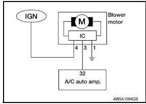
Blower Motor Circuit
Component Function Check
1.CHECK OPERATION
- Warm up the engine.
- Operate the fan control dial. Check that the fan speed and indicator are switched for all fan speeds.
Diagnosis Procedure
1.CHECK WITH SELF-DIAGNOSIS FUNCTION OF CONSULT
- Using CONSULT, perform "SELF-DIAGNOSIS RESULTS" of HVAC.
- Check if any DTC No. is displayed in the self-diagnosis results.
NOTE: If DTC is displayed along with DTC U1000 or U1010, first diagnose the DTC U1000 or U1010
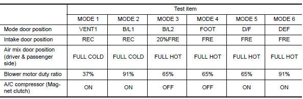
2.CHECK WITH ACTIVE TEST OF CONSULT
- Using CONSULT, perform "HVAC TEST""ACTIVE TEST" of HVAC to check each output device. Refer to HAC-129, "CONSULT Function". NOTE: Perform the ACTIVE TEST after starting the engine, because the A/C compressor is operating.
- Check that the blower motor control signal changes according to each indicator signal.
NOTE: Perform the inspection of each output device after starting the engine because the A/C compressor is operating.
3.CHECK FUSE
Check 15A fuses (Nos. 21 and 22) located in fuse block (J/B).
4.CHECK POWER SUPPLY FOR BLOWER MOTOR
- Turn ignition switch OFF.
- Disconnect blower motor connector.
- Turn ignition switch ON.
- Check voltage between blower motor harness connector M31 terminal 4 and ground.
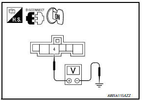
4 - Ground: Battery voltage
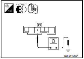
5.CHECK BLOWER MOTOR GROUND CIRCUIT
- Turn ignition switch OFF.
- Check continuity between blower motor harness connector M31 terminal 1 and ground.
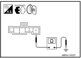
1 - Ground: Continuity should exist.
6.CHECK BLOWER MOTOR CIRCUIT CONTINUITY
- Disconnect A/C auto amp. connector.
- Check continuity between blower motor harness connector M31 (A) terminal 3 and A/C auto amp. harness connector M37 (B) terminal 32.
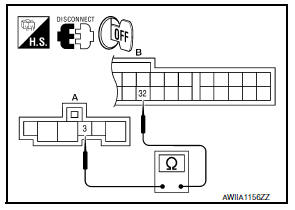
3 - 32: Continuity should exist.
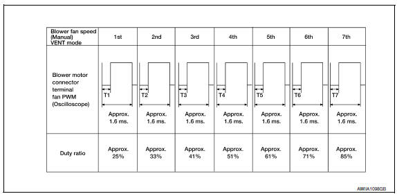
7.CHECK A/C AUTO AMP. OUTPUT SIGNAL
- Reconnect blower motor connector and A/C auto amp. connector.
- Turn ignition switch ON.
- Set MODE switch to the VENT position.
- Check the output waveform between blower motor harness connector M31 terminal 3 and ground using an oscilloscope, while varying the fan speed from 1 to 7.
8.REPLACE FUSES
- Replace fuses.
- Activate the blower motor.
9.CHECK BLOWER MOTOR POWER SUPPLY CIRCUIT FOR SHORT
- Turn ignition switch OFF.
- Disconnect blower motor harness connector.
- Check continuity between blower motor harness connector M31 terminal 4 and ground.
4 - Ground: Continuity should not exist.
10.CHECK POWER SUPPLY OF THE FRONT BLOWER MOTOR RELAY
- Turn the ignition switch OFF.
- Remove the front blower motor relay.
- Turn the ignition switch ON.
- Check the voltage between front blower motor relay harness connector J-4 terminals 2, 3 and ground.
2, 3 - Ground: Battery voltage
11.CHECK FRONT BLOWER MOTOR RELAY GROUND CIRCUIT
- Turn ignition switch OFF.
- Check continuity between front blower motor relay harness connector J-4 terminal 1 and ground.
1 - Ground: Continuity should exist.
12.CHECK BLOWER MOTOR SUPPLY CIRCUIT FOR OPEN
Check continuity between blower motor harness connector M31 terminal 4 and front blower motor relay harness connector J-4 terminal 5.
5 - 4: Continuity should exist.
 B263D, B263E, B263F intake door motor
Description
COMPONENT DESCRIPTION
Intake Door Motor
The intake door motor (1) is attached to the blower unit.
It rotates so that air is drawn from inlets set by the A/C auto
amp.
Motor ...
 Magnet clutch
Description
SYSTEM DESCRIPTION
A/C auto amp. controls A/C compressor operation by ambient temperature and
signal from ECM.
Low Temperature Protection Control
A/C auto amp. will turn the A/C co ...
Other materials:
Wiring diagram
SUNROOF SYSTEM
Wiring Diagram
...
Uniform tire quality grading
DOT (Department of Transportation) Quality
Grades: All passenger car tires must conform to
federal safety requirements in addition to these
grades.
Quality grades can be found where applicable on
the tire sidewall between tread shoulder and
maximum section width. For example:
Treadwear 200 ...
Rocker Cover
Exploded View
Camshaft position sensors (LH)
O-rings
Camshaft position sensors (RH)
O-rings
Rocker cover (RH)
Rocker cover gasket (RH)
Rocker cover gasket (LH)
Rocker cover (LH)
Refer to INSTALLATION
Front
Removal and Installation (LH)
REMOVAL
Remove the ...
Nissan Maxima Owners Manual
- Illustrated table of contents
- Safety-Seats, seat belts and supplemental restraint system
- Instruments and controls
- Pre-driving checks and adjustments
- Monitor, climate, audio, phone and voice recognition systems
- Starting and driving
- In case of emergency
- Appearance and care
- Do-it-yourself
- Maintenance and schedules
- Technical and consumer information
Nissan Maxima Service and Repair Manual

0.0068