Nissan Maxima Service and Repair Manual: Magnet clutch
Description
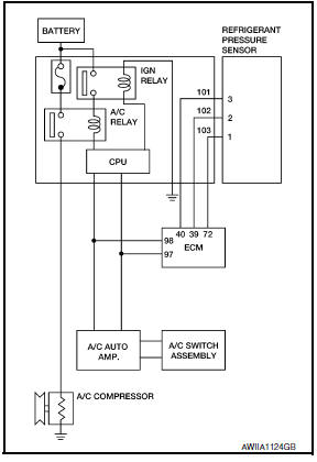
SYSTEM DESCRIPTION
A/C auto amp. controls A/C compressor operation by ambient temperature and signal from ECM.
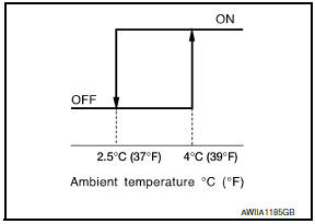
Low Temperature Protection Control A/C auto amp. will turn the A/C compressor ON or OFF as determined by a signal detected by ambient sensor.
When ambient temperature is greater than 4C (39F), the A/C compressor turns ON. The A/C compressor turns OFF when ambient temperature is less than 2.5C (37F).
Component Function Check
1.FUNCTION INSPECTIONS
- Press AUTO switch. AUTO is indicated on the display.
- Press the A/C switch.
- Check that the indicator of the A/C switch turns on. Check visually and by sound that the A/C compressor is operating. (The discharge air temperature or fan speed varies depending on the ambient temperature, in-vehicle temperature, and temperature setting.)
- Press the A/C switch again.
- Check that the indicator of the A/C switch turns OFF. Check visually and by sound that the A/C compressor stops.
Diagnosis Procedure
SYMPTOM: Magnet clutch does not engage when A/C switch is ON.
1.INSPECTION IN AUTO ACTIVE TEST MODE
Perform "AUTO ACTIVE TEST".
2.CHECK POWER SUPPLY FOR A/C COMPRESSOR
- Turn ignition switch OFF.
- Disconnect A/C compressor connector.
- Start engine and press A/C switch.
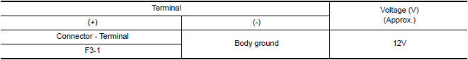
- Check voltage between A/C compressor harness connector F3 terminal 1 and ground.
3.CHECK FUSE
Check 10A fuse (No. 41) located in IPDM E/R.
4.CHECK CIRCUIT CONTINUITY BETWEEN A/C RELAY IN IPDM E/R AND A/C COMPRESSOR
- Turn ignition switch OFF.
- Disconnect IPDM E/R connector F10 and A/C compressor connector F3.
- Check continuity between A/C compressor harness connector F3 (A) terminal 1 and IPDM E/R harness connector F10 (B) terminal 48.
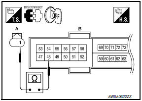
1 - 48: Continuity should exist.
5.CHECK A/C COMPRESSOR CIRCUIT FOR SHORT
Check continuity between A/C compressor harness connector F3 terminal 1 and ground.
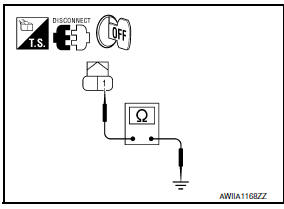
1 - Ground: Continuity should not exist.
6.CHECK WITH SELF-DIAGNOSIS FUNCTION OF CONSULT
- Using CONSULT, perform "SELF-DIAGNOSIS RESULTS" of HVAC.
- Check if any DTC No. is displayed in the self-diagnosis results.
NOTE: If DTC is displayed along with DTC U1000 or U1010, first diagnose the DTC U1000 or U1010.
7.CHECK A/C AUTO AMP. INPUT SIGNAL
Using CONSULT, check "On/Off" of "COMP REQ SIG" and "FAN REQ SIG" in "DATA MONITOR" of HVAC.
A/C SWITCH ON: COMP REQ SIG On
A/C SWITCH OFF: COMP REQ SIG Off
FAN CONTROL DIAL ON: FAN REQ SIG On
FAN CONTROL DIAL OFF: FAN REQ SIG Off
8.CHECK REFRIGERANT PRESSURE SENSOR
Check refrigerant pressure sensor.
 Blower motor
Description
COMPONENT DESCRIPTION
Brush-less Motor
The blower motor utilizes a brush-less motor with a rotating magnet.
Quietness is improved over previous motors where the brush was
the point ...
 A/C switch assembly signal circuit
Diagnosis Procedure
1.CHECK WITH SELF-DIAGNOSIS FUNCTION OF CONSULT
Using CONSULT, perform "SELF-DIAGNOSIS RESULTS" of HVAC.
Check if any DTC No. is displayed in the self-diagnosis results.
...
Other materials:
Symptom diagnosis
AUDIO SYSTEM
Symptom Table
AUDIO SYSTEM
Symptoms
Check items
Probable malfunction location
The disk cannot be removed.
Audio unit
Malfunction in audio unit.
Refer to AV-73, "Removal and
Installation".
No sound comes out ...
Diagnosis and repair workflow
Work Flow
OVERALL SEQUENCE
DETAILED FLOW
1.CHECK SYMPTOM
Check the malfunction symptoms by performing the following items.
Interview the customer to obtain the malfunction information
(conditions and environment when the malfunction occurred).
Check the symptom.
2.SELF-DIAGNOSIS (C ...
Antenna AMP
Removal and Installation
REMOVAL
Remove the rear pillar finisher RH. Refer to INT-23, "Exploded
View".
Detach the antenna amp. harness clip (A).
Disconnect the harness connectors (B) from the antenna amp.
(1).
Remove the antenna amp. screw (C) and the antenna amp. (1).
...
Nissan Maxima Owners Manual
- Illustrated table of contents
- Safety-Seats, seat belts and supplemental restraint system
- Instruments and controls
- Pre-driving checks and adjustments
- Monitor, climate, audio, phone and voice recognition systems
- Starting and driving
- In case of emergency
- Appearance and care
- Do-it-yourself
- Maintenance and schedules
- Technical and consumer information
Nissan Maxima Service and Repair Manual

0.0056