Nissan Maxima Service and Repair Manual: A/C switch assembly signal circuit
Diagnosis Procedure
1.CHECK WITH SELF-DIAGNOSIS FUNCTION OF CONSULT
- Using CONSULT, perform "SELF-DIAGNOSIS RESULTS" of HVAC.
- Check if any DTC No. is displayed in the self-diagnosis results.
NOTE: If DTC is displayed along with DTC U1000 or U1010, first diagnose the DTC U1000 or U1010.
2.CHECK RX (A/C SWITCH ASSEMBLY → A/C AUTO AMP.) CIRCUIT CONTINUITY
- Turn ignition switch OFF.
- Disconnect the A/C switch assembly and the A/C auto amp.
connectors.
- Check continuity between A/C switch assembly harness connector M104 (A) terminal 4 and A/C auto amp. harness connector M37 (B) terminal 7.
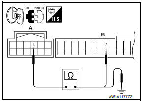
4 - 7: Continuity should exist.
- Check continuity between A/C switch assembly harness connector M104 (A) terminal 4 and ground.
4 - Ground: Continuity should not exist.
3.CHECK TX (A/C AUTO AMP. → A/C SWITCH ASSEMBLY) CIRCUIT CONTINUITY
- Check continuity between A/C switch assembly harness connector M104 (A) terminal 3 and A/C auto amp. harness connector M37 (B) terminal 6.
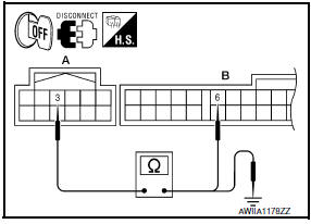
3 - 6: Continuity should exist.
- Check continuity between A/C switch assembly harness connector M104 (A) terminal 3 and ground.
3 - Ground: Continuity should not exist.
 Magnet clutch
Description
SYSTEM DESCRIPTION
A/C auto amp. controls A/C compressor operation by ambient temperature and
signal from ECM.
Low Temperature Protection Control
A/C auto amp. will turn the A/C co ...
 Power supply and ground circuit
A/C AUTO AMP.
A/C AUTO AMP.: Description
COMPONENT DESCRIPTION
A/C Auto Amp. (Air Conditioner Automatic Amplifier)
The A/C auto amp. (1) has a built-in microcomputer that processes
informatio ...
Other materials:
Door mirror motor
Description
It makes mirror face operate from side to side and up and down with the
electric power that automatic drive positioner control unit supplies.
Component Function Chec
1. CHECK DOOR MIRROR MOTOR FUNCTION
Check the operation with "MIRROR MOTOR RH" and "MIRROR MOTOR LH" in "ACTIVE
TE ...
AV control unit
Reference Value
VALUES ON THE DIAGNOSIS TOOL
CONSULT data monitor item
TERMINAL LAYOUT
PHYSICAL VALUES
*1 With satellite radio
DTC Index
Self-diagnosis results display item
...
Hands-free phone system
System Diagram
System Description
Refer to the Owner's Manual for Bluetooth telephone system operating
instructions.
NOTE:
Cellular telephones must have their wireless connection set up (paired) before
using the Bluetooth telephone
system.
Bluetooth telephone system allows users ...
Nissan Maxima Owners Manual
- Illustrated table of contents
- Safety-Seats, seat belts and supplemental restraint system
- Instruments and controls
- Pre-driving checks and adjustments
- Monitor, climate, audio, phone and voice recognition systems
- Starting and driving
- In case of emergency
- Appearance and care
- Do-it-yourself
- Maintenance and schedules
- Technical and consumer information
Nissan Maxima Service and Repair Manual

0.0063