Nissan Maxima Service and Repair Manual: Power supply and ground circuit
A/C AUTO AMP.
A/C AUTO AMP.: Description
COMPONENT DESCRIPTION
A/C Auto Amp. (Air Conditioner Automatic Amplifier)
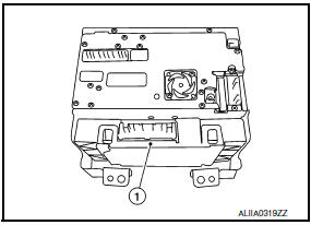
The A/C auto amp. (1) has a built-in microcomputer that processes information sent from various sensors needed for air conditioner operation. The air mix door motor(s), the mode door motor, the intake door motor, the blower motor and the A/C compressor are then controlled.
When the various switches and temperature control switches are operated, data is input to the A/C auto amp. from the AV switch assembly using CAN communication.
The A/C auto amp. is operated with control mechanisms. Signals from various switches and Potentio Temperature Control (PTC) are directly entered into the A/C auto amp.
Power Supply and Ground Circuit for A/C Auto Amp.
A/C AUTO AMP.: Component Function Check
1.CHECK OPERATION
- Press the AUTO switch, and then check that "AUTO" is shown on the display.
- Operate the temperature control switch (driver side). Check that the fan speed or outlet changes. (The discharge air temperature or fan speed varies depending on the ambient temperature, in-vehicle temperature, and temperature setting.)
A/C AUTO AMP.: Diagnosis Procedure
1.CHECK A/C AUTO AMP. POWER SUPPLY
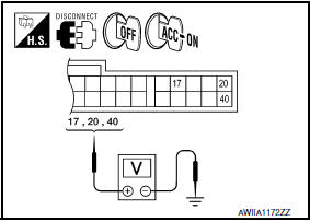
- Turn ignition switch OFF.
- Disconnect the A/C auto amp. connector.
- Turn ignition switch ON.
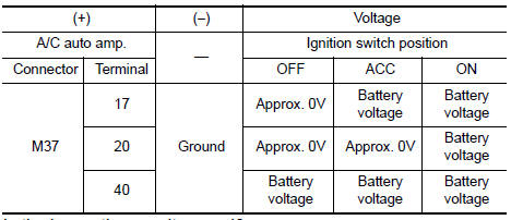
- Check voltage between A/C auto amp. harness connector M37 terminals 17, 20, 40 and ground.
2.CHECK FUSE
Check 10A fuses [Nos. 3, 6 and 17, located in the fuse block (J/B)].
3.CHECK A/C AUTO AMP. GROUND CIRCUIT
- Turn ignition switch OFF.
- Check continuity between A/C auto amp. harness connector M37 terminals 19, 39 and ground.
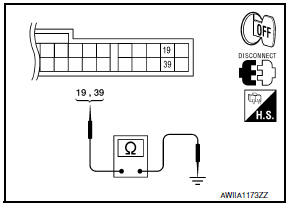
19, 39 - Ground: Continuity should exist
A/C SWITCH ASSEMBLY
A/C SWITCH ASSEMBLY: Component Function Check
1.CHECK OPERATION
- Press the AUTO switch, and then check that "AUTO" is shown on the display.
- Operate the temperature control switch (driver side). Check that the fan speed or outlet changes. (The discharge air temperature or fan speed varies depending on the ambient temperature, in-vehicle temperature, and temperature setting.)
A/C SWITCH ASSEMBLY: Diagnosis Procedure
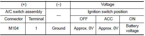
1.CHECK A/C SWITCH ASSEMBLY POWER SUPPLY
- Disconnect the A/C switch assembly connector.
- Turn ignition switch ON.
- Check voltage between A/C switch assembly harness connector M104 terminal 1 and ground.
2.CHECK FUSE
Check 10A fuse [No.3, located in the fuse block (J/B)].
3.CHECK A/C SWITCH ASSEMBLY GROUND CIRCUIT
- Turn ignition switch OFF.
- Check continuity between A/C switch assembly harness connector M104 terminal 2 and ground.
2 - Ground: Continuity should exist.
A/C DISPLAY UNIT
A/C DISPLAY UNIT: Diagnosis Procedure
1.CHECK A/C DISPLAY UNIT POWER SUPPLY CIRCUIT
- Disconnect the A/C display unit connector.
- Turn ignition switch ON.
- Check voltage between A/C display unit harness connector M101 terminal 6 and ground.
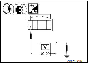
6 - Ground: Battery voltage
2.CHECK GROUND CIRCUIT FOR A/C DISPLAY UNIT
- Turn ignition switch OFF.
- Check continuity between A/C display unit harness connector M101 terminal 1 and ground.
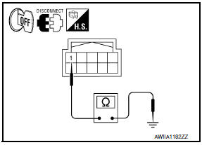
1 - Ground: Continuity should exist
 A/C switch assembly signal circuit
Diagnosis Procedure
1.CHECK WITH SELF-DIAGNOSIS FUNCTION OF CONSULT
Using CONSULT, perform "SELF-DIAGNOSIS RESULTS" of HVAC.
Check if any DTC No. is displayed in the self-diagnosis results.
...
 ECU diagnosis information
A/C AUTO AMP.
Reference Value
VALUES ON THE DIAGNOSIS TOOL
CONSULT MONITOR ITEM
A/C AUTO AMP. HARNESS CONNECTOR TERMINAL LAYOUT
TERMINALS AND REFERENCE VALUES FOR A/C AUTO AMP.
D ...
Other materials:
Navigation Swipe to Meter
Turn-by-turn route guidance can also be viewed
in the vehicle information display by using Navigation
Swipe to Meter. This can be done by
programming a route, touching the turn-by-turn
route icon on the center display, and swiping
towards the general direction of the vehicle information
di ...
Interior room lamp control system
System Diagram
System Description
OUTLINE
Interior room lamps* are controlled by interior room lamp timer
control function of BCM.
*:Front room/map lamp assembly, foot lamps and
rear personal lamps (when front room/map lamp assembly switch is in DOOR
position).
Trunk room lamp is ...
Washer level switch
Removal and Installation
REMOVAL
Position the RH front fender protector back. Refer to EXT-24,
"Removal and Installation".
Remove the engine under cover.
Remove the RH front fender protector side cover. Refer to EXT-24,
"Removal and Installation".
Disconnect the front washer level ...
Nissan Maxima Owners Manual
- Illustrated table of contents
- Safety-Seats, seat belts and supplemental restraint system
- Instruments and controls
- Pre-driving checks and adjustments
- Monitor, climate, audio, phone and voice recognition systems
- Starting and driving
- In case of emergency
- Appearance and care
- Do-it-yourself
- Maintenance and schedules
- Technical and consumer information
Nissan Maxima Service and Repair Manual

0.0079