Nissan Maxima Service and Repair Manual: Door mirror remote control switch
CHANGEOVER SWITCH
CHANGEOVER SWITCH : Description
Changeover switch is integrated into door mirror remote control switch.
Changeover switch has three positions (L, N and R).
It changes door mirror motor operation by transmitting control signal to automatic drive positioner control unit.
CHANGEOVER SWITCH : Component Function Check
1. CHECK FUNCTION
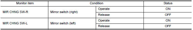
- Select "MIR CHNG SW-R", "MIR CHNG SW-L" in "DATA MONITOR" mode with CONSULT.
- Check changeover switch signal under the following conditions.
CHANGEOVER SWITCH : Diagnosis Procedure
1. CHECK CHANGEOVER SWITCH SIGNAL
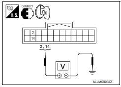
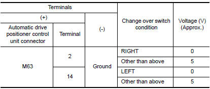
- Turn ignition switch ON.
- Check voltage between automatic drive positioner control unit connector and ground.
2. CHECK HARNESS CONT
- Turn ignition switch OFF.
- Disconnect automatic drive positioner control unit and door mirror remote control switch.
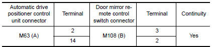
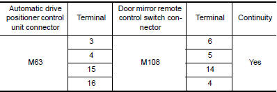
- Check continuity between automatic drive positioner control unit connector and door mirror remote control switch connector.
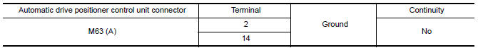
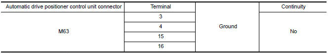
- Check continuity between automatic drive positioner control unit connector and ground
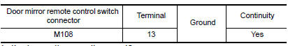
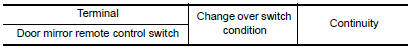
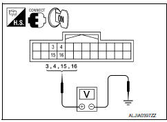
3. CHECK DOOR MIRROR REMOTE CONTROL SWITCH GROUND CIRCUIT
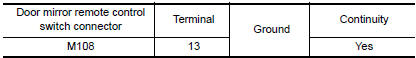
Check continuity between door mirror remote control switch connector and ground.
4. CHECK CHANGEOVER SWITCH
Check changeover switch.
5. CHECK INTERMITTENT INCIDENT
Check intermittent incident
CHANGEOVER SWITCH : Component Inspection
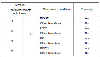
1. CHECK CHANGEOVER SWITCH
Check door mirror remote control switch.
MIRROR SWITCH
MIRROR SWITCH : Description
It transmits mirror face adjust operation to automatic drive positioner control unit.
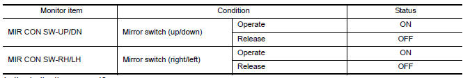
MIRROR SWITCH : Component Function Check
1. CHECK FUNCTION
- Select "MIR CON SW-UP/DN","MIR CON SW-RH/LH " in "DATA MONITOR" mode with CONSULT.
- Check mirror switch signal under the following conditions.
MIRROR SWITCH : Diagnosis Procedure
1. CHECK MIRROR SWITCH FUNCTION
- Turn ignition switch ON.
- Check voltage between automatic drive positioner control unit connector and grou

2. CHECK HARNESS CONTINUITY
- Turn ignition switch OFF.
- Disconnect automatic drive positioner control unit and door mirror remote control switch.
- Check continuity between automatic drive positioner control unit connector and door mirror remote control switch connector.
- Check continuity between automatic drive positioner control unit connector and ground.
3. CHECK DOOR MIRROR REMOTE CONTROL SWITCH GROUND CIRCUIT
Check continuity between door mirror remote control switch connector and ground.
4. CHECK MIRROR SWITCH
Check mirror switch.
5. CHECK INTERMITTENT INCIDENT
Check intermittent incident.
MIRROR SWITCH : Component Inspection
1. CHECK MIRROR SWITCH
Check door mirror remote control switch
 Seat memory switch
Description
Seat memory switch is installed to the front door LH trim. The operation
signal is input to the driver seat control unit when the seat memory switch
is operated.
Component Function C ...
 Power seat switch ground circuit
Diagnosis Procedure
1. CHECK POWER SEAT SWITCH LH GROUND CIRCUIT
Turn ignition switch OFF.
Disconnect power seat switch LH.
Check continuity between power seat switch LH connector and
...
Other materials:
Basic inspection
DIAGNOSIS AND REPAIR WORKFLOW
Work Flow
OVERALL SEQUENCE
DETAILED FLOW
1.INTERVIEW FOR MALFUNCTION
Find out what the customer's concerns are.
2.SYMPTOM CHECK
Verify the symptom from the customer's information.
3.BASIC INSPECTION
Check the operation of each part. Check if any concerns occu ...
Jacking up vehicle and removing the damaged tire
WARNING
Never get under the vehicle while it is
supported only by the jack. If it is necessary
to work under the vehicle, support
it with safety stands.
Use only the jack provided with your
vehicle to lift the vehicle. Do not use the
jack provided with your vehicle on other
veh ...
Interior trunk access
The trunk can be accessed from the passenger
side of the rear seat.
The rear seat can be locked using the mechanical
key to prevent unauthorized access. For additional
information, refer to "Keys" in this section.
1. Move the front passenger seat to the most
forward position.
2. Open th ...
Nissan Maxima Owners Manual
- Illustrated table of contents
- Safety-Seats, seat belts and supplemental restraint system
- Instruments and controls
- Pre-driving checks and adjustments
- Monitor, climate, audio, phone and voice recognition systems
- Starting and driving
- In case of emergency
- Appearance and care
- Do-it-yourself
- Maintenance and schedules
- Technical and consumer information
Nissan Maxima Service and Repair Manual

0.0054