Nissan Maxima Service and Repair Manual: B263D, B263E, B263F intake door motor
Description
COMPONENT DESCRIPTION
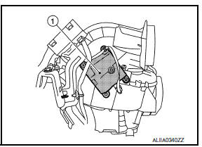
Intake Door Motor
- The intake door motor (1) is attached to the blower unit.
- It rotates so that air is drawn from inlets set by the A/C auto
amp.
Motor rotation is conveyed to a lever which activates the intake door.
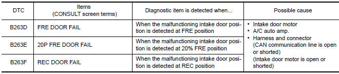
DTC Logic
DTC DETECTION LOGIC
NOTE: If DTC is displayed along with DTC U1000 or U1010, first diagnose the DTC U1000 or U1010.
DTC CONFIRMATION PROCEDURE
1.CHECK WITH SELF-DIAGNOSIS FUNCTION OF CONSULT
- Using CONSULT, perform "SELF-DIAGNOSIS RESULTS" of HVAC.
- Check if any DTC No. is displayed in the self-diagnosis results.
NOTE: If DTC is displayed along with DTC U1000 or U1010, first diagnose the DTC U1000 or U1010.
2.FUNCTION INSPECTION
- Press the REC (
 )
switch, indicator is turned ON.
)
switch, indicator is turned ON. - Listen for intake door position change. (Slight change of blower sound can be heard.)
- Press the FRE (
 )
switch, indicator is turned ON.
)
switch, indicator is turned ON. - Listen for intake door position change. (Slight change of blower sound can be heard.)
Diagnosis Procedure
1.CHECK INTAKE DOOR MOTOR POWER SUPPLY
- Turn ignition switch ON.
- Check voltage between intake door motor harness connector M126 terminal 1 and ground.
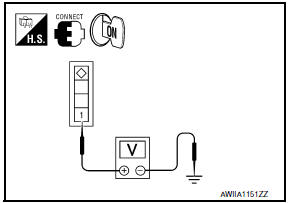
1 - Ground: Battery Voltage
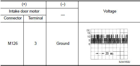
2.CHECK SIGNAL FOR INTAKE DOOR MOTOR
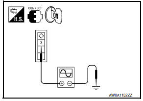
Confirm A/C LAN signal between intake door motor harness connector M126 terminal 3 and ground using an oscilloscope.
3.CHECK INTAKE DOOR MOTOR GROUND CIRCUIT
- Turn ignition switch OFF.
- Disconnect intake door motor connector.
- Check continuity between intake door motor harness connector M126 terminal 2 and ground.
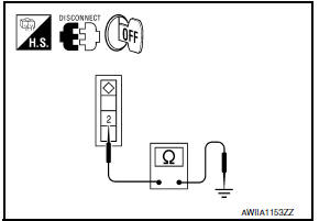
2 - Ground: Continuity should exist.
 B2636, B2637, B2638, B2639, B2654, B2655 mode door motor
Description
COMPONENT DESCRIPTION
Mode Door Motor
The mode door motor (1) is attached to the heater & cooling unit
assembly.
It rotates so that air is discharged from the outlet set by t ...
 Blower motor
Description
COMPONENT DESCRIPTION
Brush-less Motor
The blower motor utilizes a brush-less motor with a rotating magnet.
Quietness is improved over previous motors where the brush was
the point ...
Other materials:
B2578, B2579 in-vehicle sensor
Description
In-vehicle Sensor
The in-vehicle sensor (1) is located on instrument lower cover
(LH).
It converts variations in compartment air temperature drawn from
the aspirator into a resistance value. It is then input into the A/C
auto amp.
In-vehicle Sensor Circuit
Aspira ...
Both side headlamps do not switch to high beam
Description
The headlamps (both sides) do not switch to high beam when the lighting
switch is in the HI or PASS setting.
Diagnosis Procedure
1.COMBINATION SWITCH (LIGHTING AND TURN SIGNAL SWITCH) INSPECTION
Check the combination switch (lighting and turn signal switch).
2.CHECK HEADLAMP (HI) ...
Precautions on cruise control
1. CANCEL switch
2. RES+ switch
3. SET- switch
4. ON/OFF cruise switch
If the cruise control system malfunctions, it
cancels automatically.
WARNING
Do not use the cruise control when driving
under the following conditions:
When it is not possible to keep the
vehicle at ...
Nissan Maxima Owners Manual
- Illustrated table of contents
- Safety-Seats, seat belts and supplemental restraint system
- Instruments and controls
- Pre-driving checks and adjustments
- Monitor, climate, audio, phone and voice recognition systems
- Starting and driving
- In case of emergency
- Appearance and care
- Do-it-yourself
- Maintenance and schedules
- Technical and consumer information
Nissan Maxima Service and Repair Manual

0.0058