Nissan Maxima Service and Repair Manual: Slip indicator lamp
Description
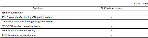
Component Function Check
1.CHECK SLIP INDICATOR LAMP OPERATION
Check that the lamp illuminates for approximately 2 seconds after the ignition switch is turned ON.
Diagnosis Procedure
1.CHECK SELF-DIAGNOSIS
Perform ABS actuator and electric unit (control unit) self-diagnosis
2.CHECK COMBINATION METER
Check if the indication and operation of combination meter are normal
Special Repair Requirement
1.ADJUSTMENT OF STEERING ANGLE SENSOR NEUTRAL POSITION
Always perform the neutral position adjustment for the steering angle sensor, when replacing the ABS actuator and electric unit (control unit).
 VDC off indicator lamp
Description
Component Function Check
1.VDC OFF INDICATOR LAMP OPERATION CHECK 1
Check that the lamp illuminates for approximately 2 seconds after the
ignition switch is turned ON.
2.VDC OFF ...
 ECU diagnosis information
ABS ACTUATOR AND ELECTRIC UNIT (CONTROL UNIT)
Reference Value
VALUES ON THE DIAGNOSIS TOOL
CAUTION:
The display shows the control unit calculation data, so a normal value might be
displayed eve ...
Other materials:
System Description
NOISE, VIBRATION, AND HARSHNESS (NVH) TROUBLESHOOTING
NVH Troubleshooting - Engine Noise
Camshaft bearing noise
Piston pin noise
Piston slap noise
Main bearing noise
Connecting rod bearing noise
Drive belt noise (Sticking/Slipping)
Drive belt noise (Slipping)
Water pump n ...
System maintenance
CAUTION
Do not use alcohol, benzine or thinner
to clean the camera. This will cause
discoloration.
Do not damage the camera as the monitor
screen may be adversely affected.
If dirt, rain or snow accumulates on any of the
cameras 1 , the MOD system may not operate
properly. Clean ...
Seats
WARNING
Do not ride in a moving vehicle when
the seatback is reclined. This can be
dangerous. The shoulder belt will not
be against your body. In an accident,
you could be thrown into it and receive
neck or other serious injuries. You
could also slide under the lap belt and
recei ...
Nissan Maxima Owners Manual
- Illustrated table of contents
- Safety-Seats, seat belts and supplemental restraint system
- Instruments and controls
- Pre-driving checks and adjustments
- Monitor, climate, audio, phone and voice recognition systems
- Starting and driving
- In case of emergency
- Appearance and care
- Do-it-yourself
- Maintenance and schedules
- Technical and consumer information
Nissan Maxima Service and Repair Manual

0.0073