Nissan Maxima Service and Repair Manual: VDC off indicator lamp
Description

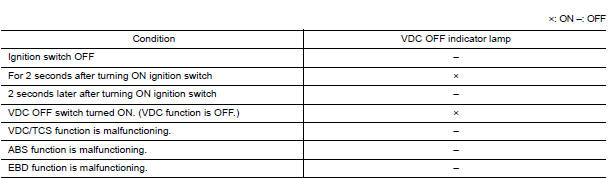
Component Function Check
1.VDC OFF INDICATOR LAMP OPERATION CHECK 1
Check that the lamp illuminates for approximately 2 seconds after the ignition switch is turned ON.
2.VDC OFF INDICATOR LAMP OPERATION CHECK 2
Check that the VDC OFF indicator lamp in the combination meter turns on/off correctly when operating the VDC OFF switch
Diagnosis Procedure
1.CHECK VDC OFF SWITCH
Check that the VDC OFF indicator lamp in the combination meter turns on/off correctly when operating the VDC OFF switch
2.CHECK SELF-DIAGNOSIS
Perform ABS actuator and electric unit (control unit) self-diagnosis
3.CHECK COMBINATION METER
Check if the indication and operation of combination meter are normal.
1.ADJUSTMENT OF STEERING ANGLE SENSOR NEUTRAL POSITION
Always perform the neutral position adjustment for the steering angle sensor, when replacing the ABS actuator and electric unit (control unit).
 Brake warning lamp
Description
NOTE:
1: Brake warning lamp will turn on in case of parking brake operation
(when switch is ON) or of brake fluid level switch operation
(when brake fluid is insufficient).
...
 Slip indicator lamp
Description
Component Function Check
1.CHECK SLIP INDICATOR LAMP OPERATION
Check that the lamp illuminates for approximately 2 seconds after the
ignition switch is turned ON.
Diagnosis Proce ...
Other materials:
B2099 ignition relay off stuck
DTC Logic
DTC DETECTION LOGIC
DTC CONFIRMATION PROCEDURE
1.PERFORM DTC CONFIRMATION PROCEDURE
Turn the power supply position to start under the following
conditions and wait for at least 1 second.
CVT selector lever is in the P (Park) or N (Neutral) position.
Depress the brake ...
Oil pump
Removal and Installation
REMOVAL
Remove the engine from the vehicle. Refer to EM-103, "Removal and
Installation".
Remove the upper oil pan. Refer to EM-37, "Removal and
Installation (Upper Oil Pan)".
Remove the timing chain. Refer to EM-64, "Removal and
Installati ...
The parking brake release warning continues sounding, or does not sound
Description
The parking brake warning buzzer sounds continuously during
vehicle travel though the parking brake is
released
The parking brake warning buzzer does not sound at all even though
driving the vehicle with the parking
brake applied.
Diagnosis Procedure
1. CHECK PARKIN ...
Nissan Maxima Owners Manual
- Illustrated table of contents
- Safety-Seats, seat belts and supplemental restraint system
- Instruments and controls
- Pre-driving checks and adjustments
- Monitor, climate, audio, phone and voice recognition systems
- Starting and driving
- In case of emergency
- Appearance and care
- Do-it-yourself
- Maintenance and schedules
- Technical and consumer information
Nissan Maxima Service and Repair Manual

0.0084