Nissan Maxima Service and Repair Manual: Audio display unit
Removal and Installation
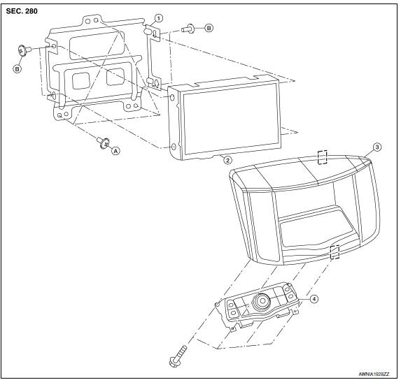
- Audio display unit bracket
- Audio display unit
- Cluster lid D
- Multifunction switch
- Audio display unit bracket screws
- Audio display unit screws
 Metal Clip
REMOVAL
- Remove the cluster lid D. Refer to IP-11, "Removal and Installation".
- Remove the audio display unit bracket screws (A).
- Pull out the audio display unit and bracket assembly (1).
- Disconnect the harness connectors from the audio display unit and bracket assembly (1) and remove.
- Remove the audio display unit screws on the sides and remove the audio display unit from the audio display unit brackets.
INSTALLATION
Installation is in the reverse order of removal.
 Multifunction switch
Removal and Installation
REMOVAL
Remove cluster lid D. Refer to IP-10, "Exploded View".
Remove the four multifunction switch screws (A) and remove the
multifunction switch (2) from ...
 USB connector
Removal and Installation
REMOVAL
Remove the center console assembly. Refer to IP-14, "Removal and
Installation".
Release the pawl from the back of the center console to remove the
USB i ...
Other materials:
B2602 shift position
Description
BCM confirms the shift position with the following 2
signals.
CVT selector lever
Speed signal from meter
DTC Logic
DTC DETECTION LOGIC
NOTE:
If DTC B2602 is displayed with DTC
U1000, first perform the trouble diagnosis for DTC U1000. Refer ...
B1065 - B1068, B1070 - B1073 passenger airbag module
Description
DTC B1065 - B1068, B1070 - B1073 PASSENGER AIR BAG MODULE
The passenger air bag module is dual stage and wired to the air bag diagnosis
sensor unit. The air bag diagnosissensor unit will monitor for opens and
shorts in detected lines to the passenger air bag module.
PART LOCATION
...
Unexpected pedal reaction
Diagnosis Procedure
1.CHECK BRAKE PEDAL STROKE
Check brake pedal stroke.
2.CHECK FUNCTION
Disconnect ABS actuator and electric unit (control unit) connector to
deactivate ABS. Check if braking force is
normal in this condition.Connect connector after inspection.
3.CHECK WHEEL SENSOR AND SEN ...
Nissan Maxima Owners Manual
- Illustrated table of contents
- Safety-Seats, seat belts and supplemental restraint system
- Instruments and controls
- Pre-driving checks and adjustments
- Monitor, climate, audio, phone and voice recognition systems
- Starting and driving
- In case of emergency
- Appearance and care
- Do-it-yourself
- Maintenance and schedules
- Technical and consumer information
Nissan Maxima Service and Repair Manual

0.0055