Nissan Maxima Service and Repair Manual: Diagnosis system (meter)
Diagnosis Description
SELF-DIAGNOSIS MODE
- Odo/trip meter and information display segment operation can be checked in self-diagnosis mode.
- Meters/gauges can be checked in self-diagnosis mode.
OPERATION PROCEDURE
- Turn the ignition switch OFF.
- While pushing the odo/trip meter switch, turn the ignition switch ON again.
- Push the odo/trip meter switch at least 3 times within 7 seconds after the ignition switch is turned ON.
- The unified meter control unit is turned to self-diagnosis mode.
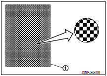
- All the segments on the odo/trip meter illuminate.
- Dots in all segments of information display LCD (1) flash alternately.
NOTE:
If any of the segments are not displayed, replace the combination meter. Refer to MWI-122, "Removal and Installation".
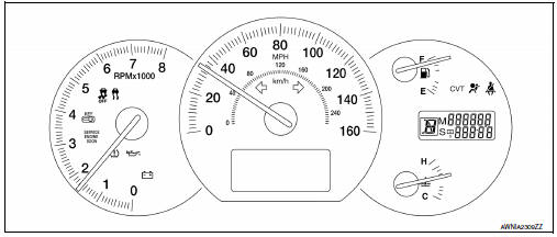
5. Push the odo/trip meter switch. Each meter/gauge should indicate as shown in the figure.
CONSULT Function (METER/M&A)
CONSULT can display each diagnostic item using the diagnostic test modes shown following.
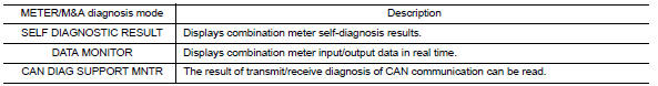
SELF-DIAG RESULTS
Display Item List Refer to MWI-51, "DTC Index".
DATA MONITOR
Display Item List
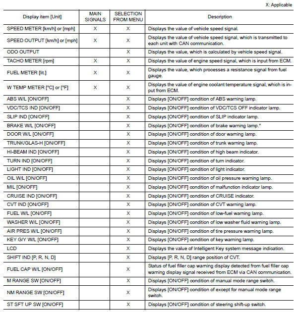
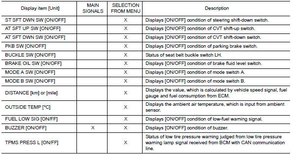
NOTE:
Some items are not available due to vehicle specification.
*: The monitor will indicate "OFF" even though the brake warning lamp is on if either of the following conditions exist.
- The parking brake is engaged
- The brake fluid level is low
 Compass
Description
DESCRIPTION
With the ignition switch in the ON position, and the mode (N) switch
ON, the compass display will indicate the direction the vehicle is
heading.
Vehicle direction is dis ...

Other materials:
Engine cooling system
The engine cooling system is filled at the factory
with a pre-diluted mixture of 50% Genuine
NISSAN Long Life Antifreeze/Coolant (blue) and
50% water to provide year-round antifreeze and
coolant protection. The antifreeze solution contains
rust and corrosion inhibitors. Additional engine
cooli ...
Turn signal and hazard warning lamps
System Diagram
System Description
BCM (Body Control Module) controls turn signal lamp (RH and LH) and
hazard warning lamp operation
Combination meter operates turn signal indicator (RH and LH)
according to CAN communication signals from BCM.
Component Parts Location
BCM M16 ...
STRG branch line circuit
Diagnosis Procedure
1.CHECK CONNECTOR
Turn the ignition switch OFF.
Disconnect the battery cable from the negative terminal.
Check the terminals and connectors of the steering angle sensor
for damage, bend and loose connection
(unit side and connector side).
2.CHECK HARNESS FOR OPE ...
Nissan Maxima Owners Manual
- Illustrated table of contents
- Safety-Seats, seat belts and supplemental restraint system
- Instruments and controls
- Pre-driving checks and adjustments
- Monitor, climate, audio, phone and voice recognition systems
- Starting and driving
- In case of emergency
- Appearance and care
- Do-it-yourself
- Maintenance and schedules
- Technical and consumer information
Nissan Maxima Service and Repair Manual

0.0058