Nissan Maxima Service and Repair Manual: System description
COMPRESSOR CONTROL FUNCTION
Description
PRINCIPLE OF OPERATION
Compressor is not activated.
Functional circuit diagram
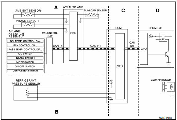
CAN (1): A/C switch signal
: Blower fan motor switch signal
CAN (2): A/C compressor request signal
Functional initial inspection chart
Fail-Safe
FAIL-SAFE FUNCTION
- If a communication error exists between the A/C auto amp., the AV control unit and the A/C and AV switch assembly for 30 seconds or longer, air conditioner is controlled under the following conditions:
Compressor: ON
Air outlet: AUTO
Air inlet: FRE (  )
)
Blower fan speed: AUTO
Set temperature: Setting before communication error occurs
Display: OFF
 Basic inspection
INSPECTION AND ADJUSTMENT
Operational Check
DESCRIPTION
The purpose of the operational check is to check that the individual system
operates normally.
Conditions: Engine running at normal operat ...
 Automatic air conditioner system
System Diagram
CONTROL SYSTEM
The control system consists of input sensors, switches, the A/C auto amp.
(microcomputer) and outputs. The
relationship of these components is as shown in the figure ...
Other materials:
Rear-facing child restraint installation using the seat belts
WARNING
The three-point seat belt with Automatic
Locking Retractor (ALR) must be used when
installing a child restraint. Failure to use the
ALR mode will result in the child restraint
not being properly secured. The restraint
could tip over or be loose and cause injury
to a child in a sudden ...
P1723 speed sensor
Description
The secondary speed sensor detects the revolution of
parking gear and generates a pulse signal. The pulse
signal is sent to the TCM, which converts it into vehicle speed.
The primary speed sensor detects the primary pulley revolution speed and sends a
signal to the TCM.
DTC Lo ...
Power supply and ground circuit
AV CONTROL UNIT
AV CONTROL UNIT : Diagnosis Procedure
1.CHECK FUSES
Check that the following fuses of the AV control unit are not blown.
2.POWER SUPPLY CIRCUIT CHECK
Disconnect AV control unit connectors M152 and M156.
Check voltage between the AV control unit connectors M152
an ...
Nissan Maxima Owners Manual
- Illustrated table of contents
- Safety-Seats, seat belts and supplemental restraint system
- Instruments and controls
- Pre-driving checks and adjustments
- Monitor, climate, audio, phone and voice recognition systems
- Starting and driving
- In case of emergency
- Appearance and care
- Do-it-yourself
- Maintenance and schedules
- Technical and consumer information
Nissan Maxima Service and Repair Manual

0.0059