Nissan Maxima Service and Repair Manual: Mode door control system
System Diagram
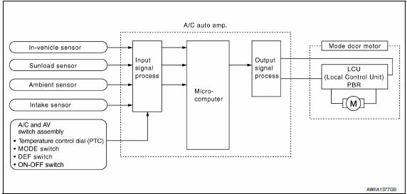
System Description
The mode door is automatically controlled by the temperature setting, ambient temperature, in-vehicle temperature, intake temperature and amount of sunload.
SYSTEM OPERATION
- The A/C auto amp. receives data from each of the sensors.
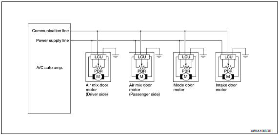
- The A/C auto amp. sends the air mix door, the mode door and the intake door opening angle data to the air mix door motor LCU(s), the mode door motor LCU and the intake door motor LCU.
- The air mix door motor(s), the mode door motor and the intake door motor read their respective signals according to the address signal. Opening angle indication signals received from the A/C auto amp. and each of the motor position sensors, are compared by the LCUs in each door motor with the existing decision and opening angles.
- Next, HOT/COLD, DEF/VENT or FRE/REC operation is selected. The newly selected data is returned to the A/C auto amp.
Door Motor Circuit
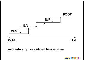
Mode Door Control Specification
Mode position can be selected manually by pressing the MODE switch or the DEF switch on the A/C and AV switch assembly. Pressing the AUTO switch allows automatic control by the A/C auto amp.
During the automatic control of a mode position, a mode door position (VENT, B/L, FOOT, or D/F) is selected based on a target air mix door opening angle and sunload sensor, calculated by the A/C auto amp. In addition, the D/F is selected to prevent windshield fogging only when ambient temperature is extremely low.
 Automatic air conditioner system
System Diagram
CONTROL SYSTEM
The control system consists of input sensors, switches, the A/C auto amp.
(microcomputer) and outputs. The
relationship of these components is as shown in the figure ...
 Air mix door control system
System Diagram
System Description
The air mix doors are automatically controlled so that in-vehicle temperature
is maintained at a predetermined
value by the temperature setting, ambient temp ...
Other materials:
B2193 chain of ECM-IMMU
Description
BCM performs the ID verification with ECM that allows the
engine to start. Start the engine if the ID is OK.
ECM prevents the engine from starting if the ID is not registered. BCM starts
the communication with ECM if
ignition switch is turned ON.
DTC Logic
DTC DETECTION LOGIC ...
Symptom diagnosis
SQUEAK AND RATTLE TROUBLE DIAGNOSES
Work Flow
CUSTOMER INTERVIEW
Interview the customer if possible, to determine the conditions that exist
when the noise occurs. Use the Diagnostic
Worksheet during the interview to document the facts and conditions when the
noise occurs and any
custome ...
Reclining motor
Description
The reclining motor is installed to the seatback assembly.
The reclining motor is activated with the driver seat control unit.
The seatback is reclined forward/backward by changing the rotation
direction of reclining motor.
Component Function Check
1. CHECK FUNCTION
Se ...
Nissan Maxima Owners Manual
- Illustrated table of contents
- Safety-Seats, seat belts and supplemental restraint system
- Instruments and controls
- Pre-driving checks and adjustments
- Monitor, climate, audio, phone and voice recognition systems
- Starting and driving
- In case of emergency
- Appearance and care
- Do-it-yourself
- Maintenance and schedules
- Technical and consumer information
Nissan Maxima Service and Repair Manual

0.0065