Nissan Maxima Service and Repair Manual: ECU diagnosis information
BCM (BODY CONTROL MODULE)
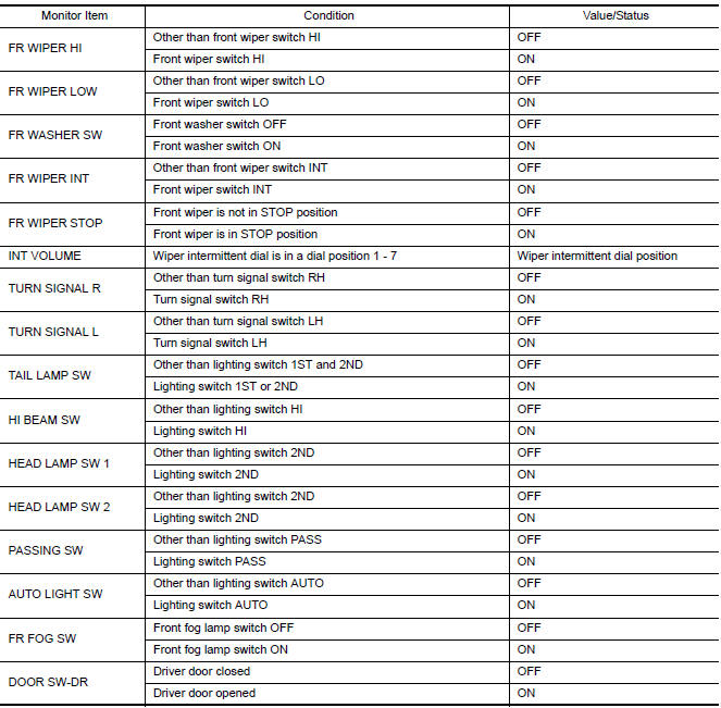
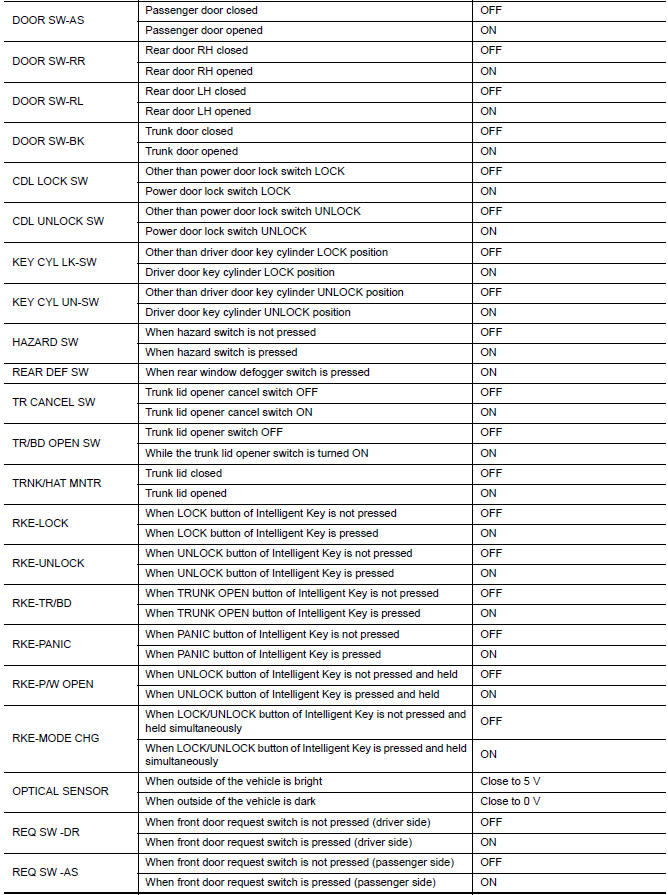
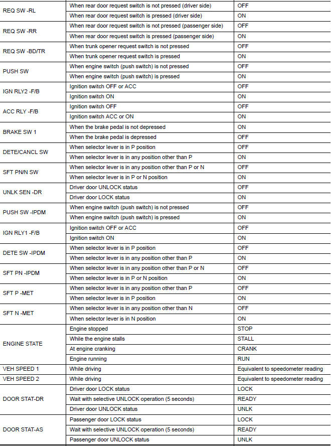
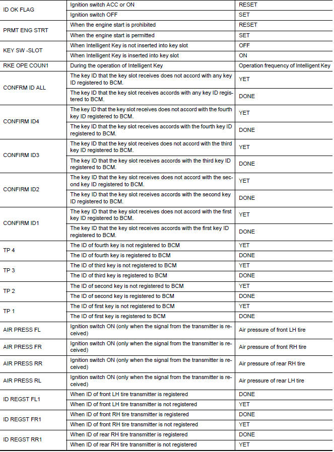
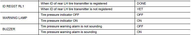
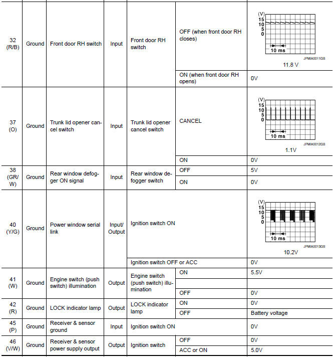
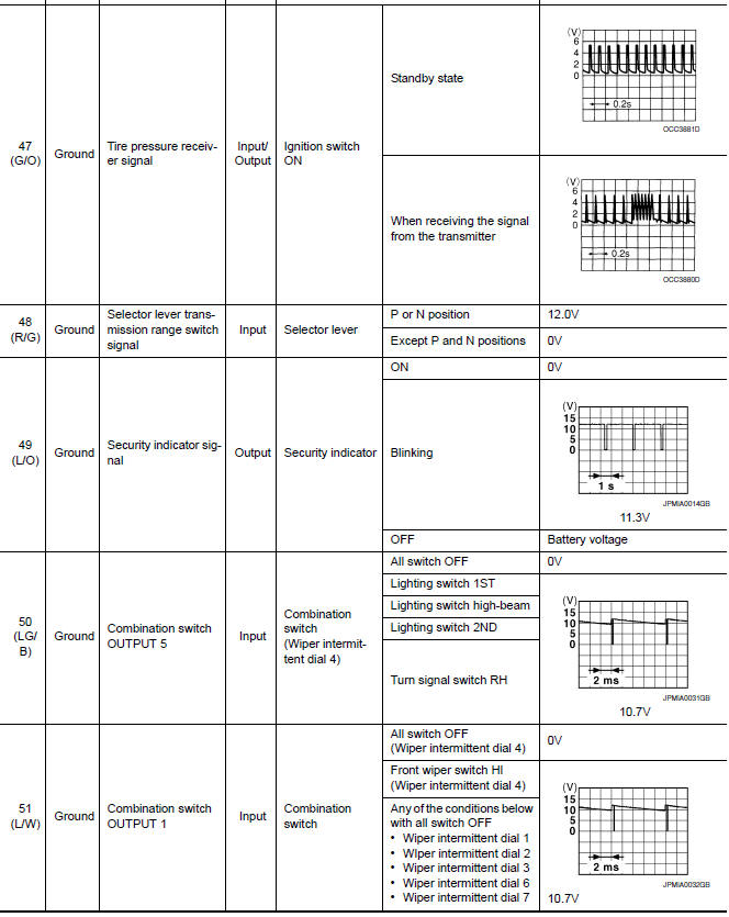
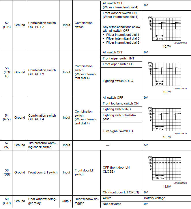
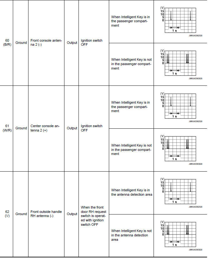
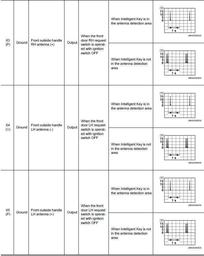
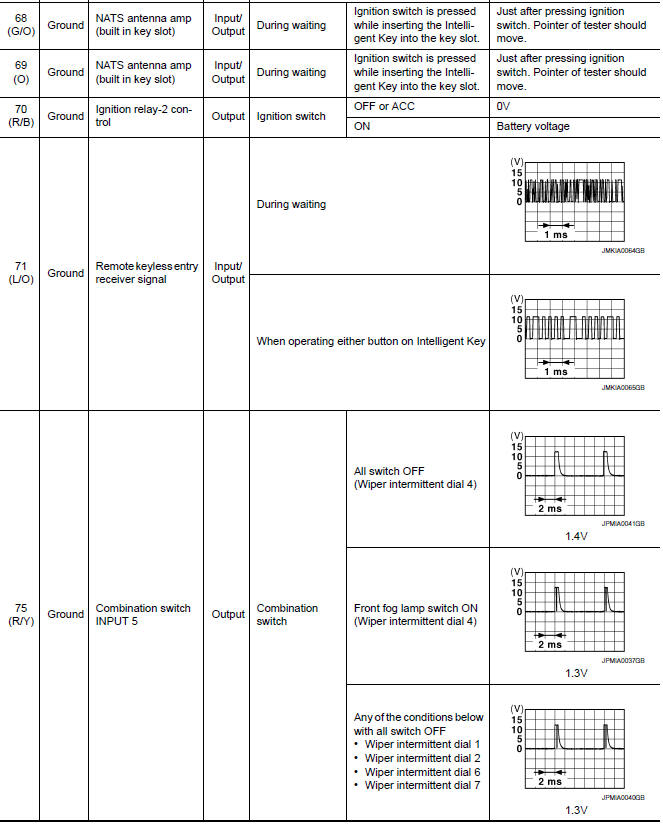
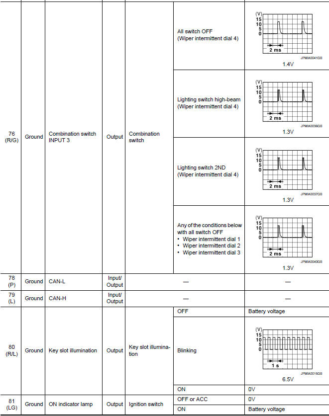
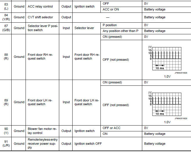
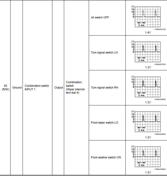
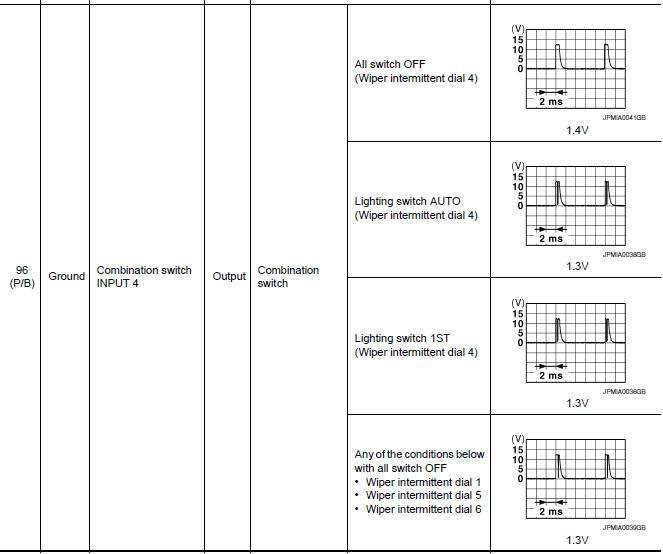
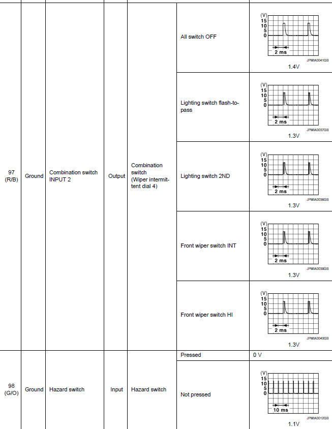
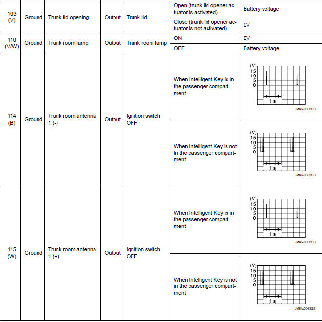
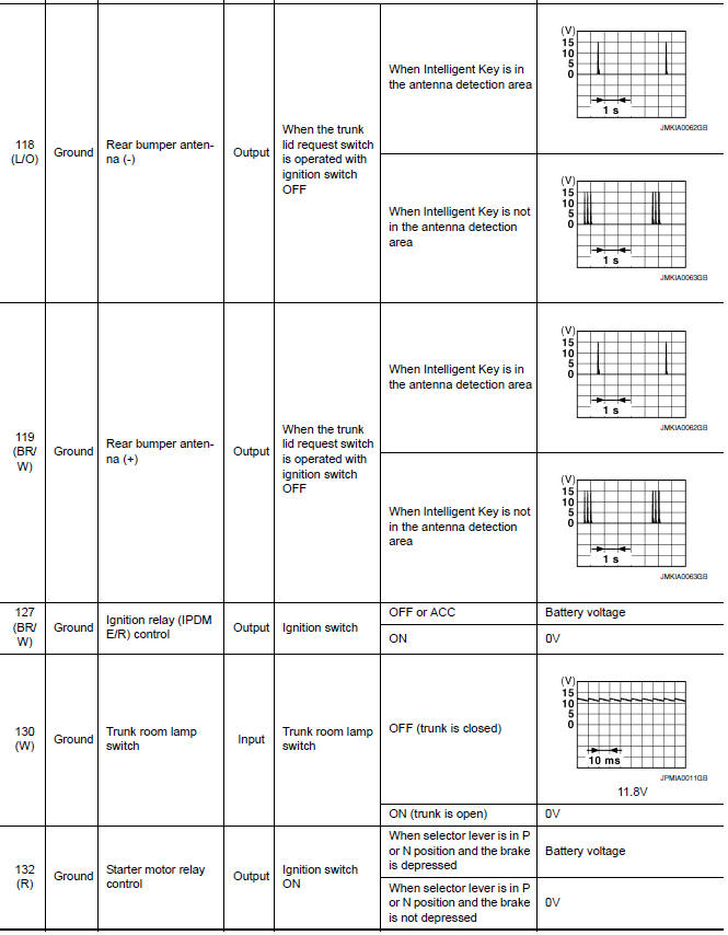
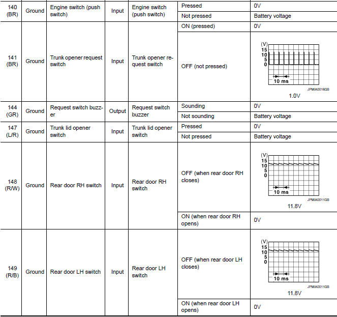
Reference Value
NOTE: The Signal Tech II Tool (J-50190) can be used to perform the following functions. Refer to the Signal Tech II User Guide for additional information.
- Activate and display TPMS transmitter IDs
- Display tire pressure reported by the TPMS transmitter
- Read TPMS DTCs
- Register TPMS transmitter IDs
- Check Intelligent Key relative signal strength
- Confirm vehicle Intelligent Key antenna signal strength
VALUES ON THE DIAGNOSIS TOOL
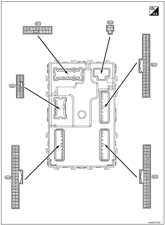
Terminal Layout
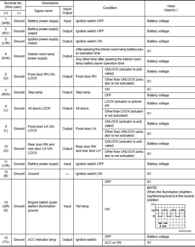
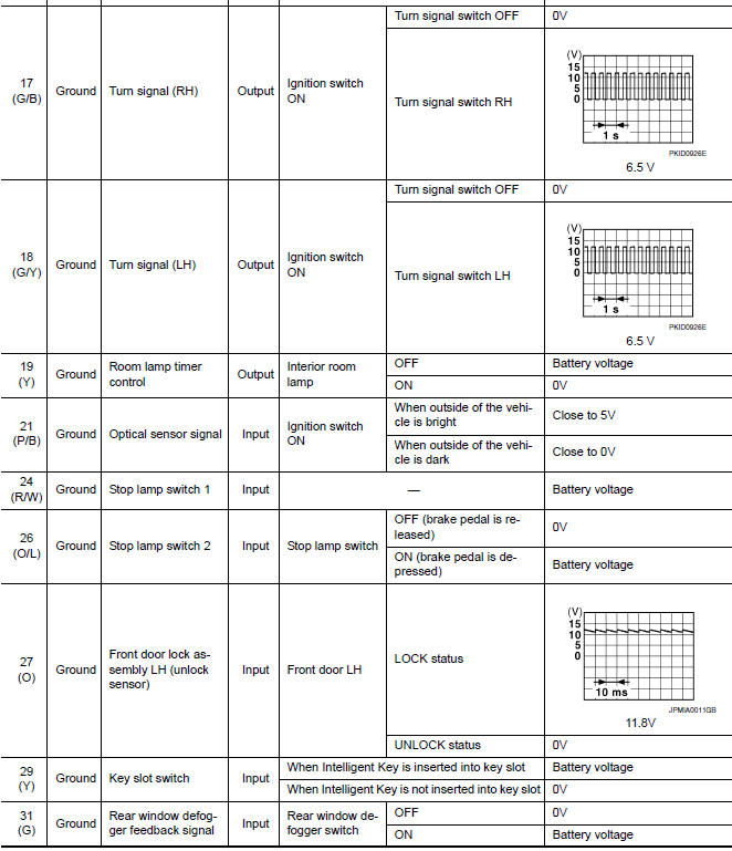
Physical Values
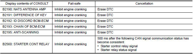
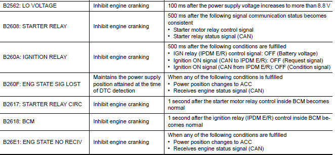
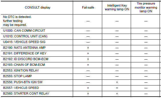
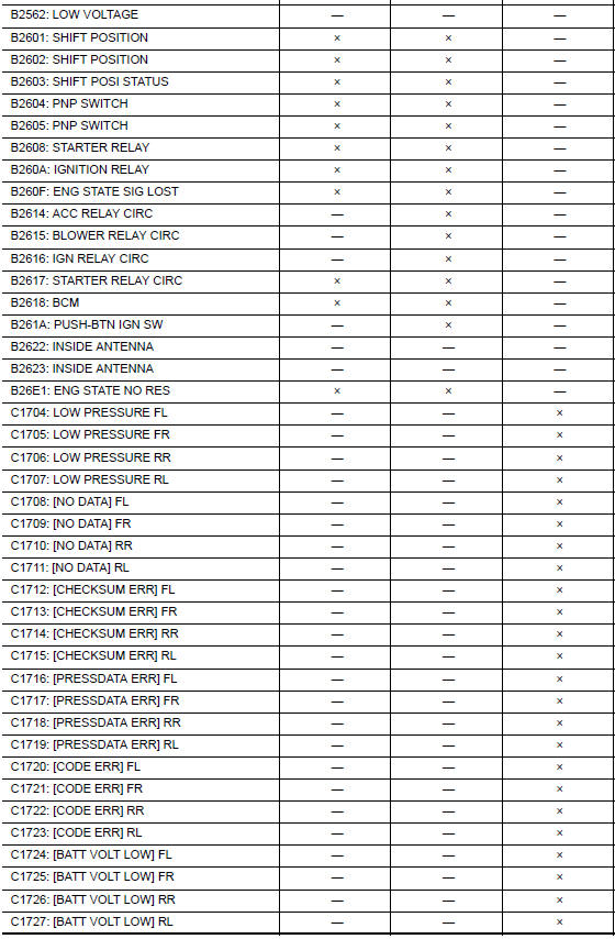
Fail Safe
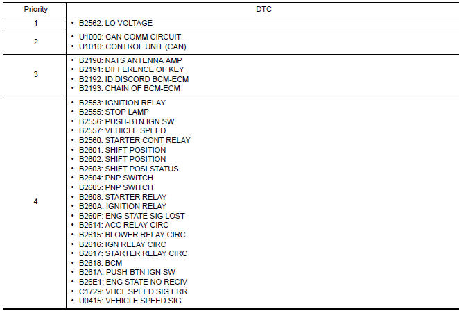
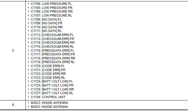
DTC Inspection Priority Chart
If some DTCs are displayed at the same time, perform inspections one by one based on the following priority chart.
DTC Index
NOTE: Details of time display
- CRNT: Displays when there is a malfunction now or after returning to the normal condition until turning ignition switch OFF → ON again.
- 1 - 39: Displayed if any previous malfunction is present when current condition is normal. It increases 1 → 2 → 3...38 → 39 after returning to the normal condition whenever ignition switch OFF → ON. The counter remains at 39 even if the number of cycles exceeds it. It is counted from 1 again when turning ignition switch OFF → ON after returning to the normal condition if the malfunction is detected again

 Push-button ignition switch illumination circuit
Description
Provides the power supply and the ground to control the push-button ignition
switch illumination.
Component Function Check
1.CHECK PUSH-BUTTON IGNITION SWITCH ILLUMINATION OPERATION
...
 Wiring diagram
...
Other materials:
Diagnosis system (bluetooth control unit)
Diagnosis Description
The Bluetooth control unit has two diagnostic checks. The first diagnostic
check is performed automatically every ignition cycle during control unit
initialization. The second diagnostic check is performed by the technician
using the steering wheel audio control switches ...
Rear window defogger system
System Diagram
System Description
Operation Description
When rear window defogger switch is turned ON while ignition
switch is ON, the A/C auto amp. (rear window
defogger switch) transmits rear window defogger switch signal to BCM.
BCM turns rear window defogger relay ON when rear ...
Door
FRONT DOOR
FRONT DOOR : Exploded View
Front door panel
Front door check link
Front door lower hinge
Front lower hinge
Grease
FRONT DOOR : Removal and Installation
CAUTION:
Use two people when removing or installing the front door
assembly due to its heavy weight. ...
Nissan Maxima Owners Manual
- Illustrated table of contents
- Safety-Seats, seat belts and supplemental restraint system
- Instruments and controls
- Pre-driving checks and adjustments
- Monitor, climate, audio, phone and voice recognition systems
- Starting and driving
- In case of emergency
- Appearance and care
- Do-it-yourself
- Maintenance and schedules
- Technical and consumer information
Nissan Maxima Service and Repair Manual

0.0068