Nissan Maxima Service and Repair Manual: Push-button ignition switch illumination circuit
Description
Provides the power supply and the ground to control the push-button ignition switch illumination.
Component Function Check
1.CHECK PUSH-BUTTON IGNITION SWITCH ILLUMINATION OPERATION
CONSULT
- Turn the ignition switch ON.
- Select "ENGINE SW ILLUMI" of BCM (INTELLGENT KEY) active test item.
- While operating the test item, check that the push-button ignition switch illumination turns ON/OFF
ON : Push-button ignition switch illumination ON
OFF : Push-button
ignition switch illumination OFF
Diagnosis Procedure
1.CHECK PUSH-BUTTON IGNITION SWITCH ILLUMINATION OPERATION
CONSULT
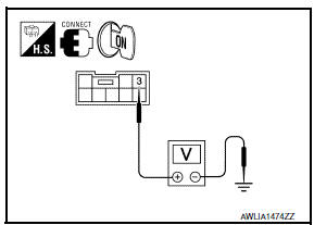
- Turn the ignition switch ON.
- Select "ENGINE SW ILLUMI" of BCM (INTELLGENT KEY) active test item.
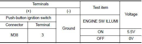
- While operating the test item, check voltage between push-button ignition switch connector M38 terminal 3 and ground.
2.CHECK PUSH-BUTTON IGNITION SWITCH ILLUMINATION POWER SUPPLY OPEN CIRCUIT
- Turn the ignition switch OFF.
- Disconnect BCM connector M18 and push-button ignition switch connector.
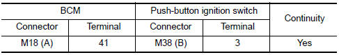
- Check continuity between BCM connector M18 (A) terminal 41 and push-button ignition switch connector M38 (B) terminal 3.
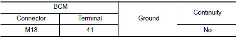
3.CHECK PUSH-BUTTON IGNITION SWITCH ILLUMINATION POWER SUPPLY SHORT CIRCUIT
Check continuity between BCM connector M18 terminal 41 and ground.
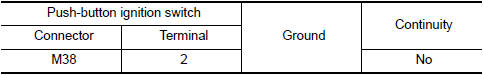
4.CHECK PUSH-BUTTON IGNITION SWITCH ILLUMINATION GROUND CIRCUIT
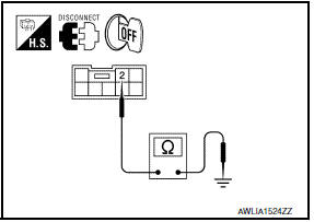
- Turn the ignition switch OFF.
- Disconnect push-button ignition switch connector.
- Check continuity between push-button ignition switch connector M38 terminal 2 and ground.
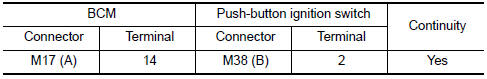
5.CHECK PUSH-BUTTON IGNITION SWITCH ILLUMINATION GROUND OPEN CIRCUIT
- Disconnect BCM connector M17.
- Check continuity between BCM connector M17 (A) terminal 14 and push-button ignition switch connector M38 (B) terminal 2.
 Trunk room lamp circuit
Description
Controls the trunk room lamp (ground side) to turn the trunk room lamp ON and
OFF.
Component Function Check
CAUTION: Before performing the diagnosis,
check that the following is nor ...
 ECU diagnosis information
BCM (BODY CONTROL MODULE)
Reference Value
NOTE: The Signal Tech II Tool (J-50190) can
be used to perform the following functions. Refer to the Signal Tech II User
Guide for additional informatio ...
Other materials:
On board diagnostic (OBD) system
Trouble Diagnosis Introduction
CAUTION:
Do not use electrical test equipment on any circuit related to
the SRS unless instructed to do so inthis Service Manual. SRS wiring
harnesses can be identified by yellow and/or orange harness connectors.
Do not attempt to repair, splice or modify ...
Remote engine start operating range
CAUTION
When the Intelligent Key battery is discharged
or other strong radio wave
sources are present near the operating
location, the Intelligent Key operating
range becomes narrower, and the Intelligent
Key may not function properly.
The remote engine start function can only be
used when t ...
Key reminder function
System Description
Key reminder is the function that prevents the key from being left in the
vehicle.
Key reminder has the following 3 functions.
Key reminder function
Operation condition
Operation
Driver door closed
Right after driver side door is close ...
Nissan Maxima Owners Manual
- Illustrated table of contents
- Safety-Seats, seat belts and supplemental restraint system
- Instruments and controls
- Pre-driving checks and adjustments
- Monitor, climate, audio, phone and voice recognition systems
- Starting and driving
- In case of emergency
- Appearance and care
- Do-it-yourself
- Maintenance and schedules
- Technical and consumer information
Nissan Maxima Service and Repair Manual

0.0061