Nissan Maxima Service and Repair Manual: Inspection and adjustment
ADDITIONAL SERVICE WHEN REPLACING CONTROL UNIT
ADDITIONAL SERVICE WHEN REPLACING CONTROL UNIT : Description
BEFORE REPLACEMENT
When replacing AV control unit, save current vehicle specification with CONSULT configuration before replacement.
AFTER REPLACEMENT
CAUTION: When replacing AV control unit, you must perform "WRITE CONFIGURATION" with CONSULT.
- Complete the procedure of "WRITE CONFIGURATION" in order.
- If you set incorrect "WRITE CONFIGURATION", incidents might occur.
- Configuration is different for each vehicle model. Confirm configuration of each vehicle model.
ADDITIONAL SERVICE WHEN REPLACING CONTROL UNIT : Special Repair Requirement
1.SAVING VEHICLE SPECIFICATION
CONSULT Configuration
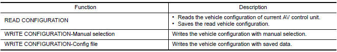
Perform "READ CONFIGURATION" to save current vehicle specification.
2.REPLACE AV CONTROL UNIT
Replace AV control unit.
3.WRITING VEHICLE SPECIFICATION
CONSULT Configuration
Perform "WRITE CONFIGURATION - Config file" or "WRITE CONFIGURATION - Manual selection" to write vehicle specification.
4.OPERATION CHECK
Check that the operation of the AV control unit and camera images (fixed guide lines and predictive course lines) are normal.
CONFIGURATION (AV CONTROL UNIT)
CONFIGURATION (AV CONTROL UNIT) : Description
- Since vehicle specifications are not included in the AV control unit after replacement, it is required to write vehicle specifications with CONSULT.
- Configuration has three functions as follows
CONFIGURATION (AV CONTROL UNIT) : Special Repair Requirement
1.WRITING MODE SELECTION
CONSULT Configuration
Select "CONFIGURATION" of AV control unit.
2.PERFORM "WRITE CONFIGURATION-CONFIG FILE"
CONSULT Configuration
Perform "WRITE CONFIGURATION-Config file".
3.PERFORM "WRITE CONFIGURATION-MANUAL SELECTION"
CONSULT Configuration
Select "WRITE CONFIGURATION-Manual selection" to write vehicle specifications into the AV control unit.
4.OPERATION CHECK
Check that the operation of the AV control unit and camera images (fixed guide lines and predictive course lines) are normal.
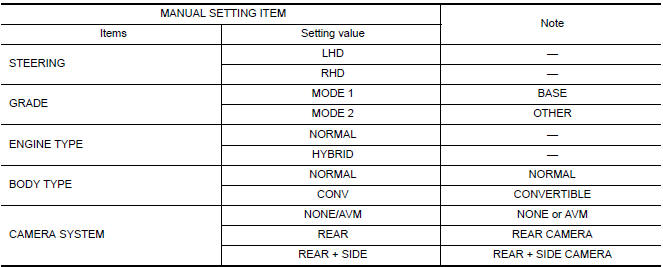
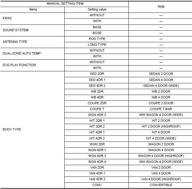
CONFIGURATION (AV CONTROL UNIT) : Configuration List
CAUTION: Check vehicle specifications before servicing.
 Diagnosis and repair workflow
Work Flow
OVERALL SEQUENCE
DETAILED FLOW
1.CHECK SYMPTOM
Check the malfunction symptoms by performing the following items.
Interview the customer to obtain the malfunction information (con ...

Other materials:
Audio system
Symptom Table
AUDIO SYSTEM
Symptoms
Check items
Probable malfunction location
The disk cannot be removed
AV control unit
Malfunction in AV control unit.
Refer to AV-311, "Removal and
Installation".
No sound comes out or the level of the sound is low.
No ...
P0138, P0158 HO2S2
Description
The heated oxygen sensor 2, after three way catalyst (manifold),
monitors the oxygen level in the exhaust gas on each bank.
Even if switching characteristics of the air fuel ratio (A/F) sensor 1
are shifted, the air-fuel ratio is controlled to stoichiometric, by the signal
...
Power consumption control system
System Diagram
System Description
OUTLINE
BCM incorporates a power saving control function that reduces the
power consumption according to the
vehicle status.
BCM switches the status (control mode) by itself with the power
saving control function. It performs the sleep
reques ...
Nissan Maxima Owners Manual
- Illustrated table of contents
- Safety-Seats, seat belts and supplemental restraint system
- Instruments and controls
- Pre-driving checks and adjustments
- Monitor, climate, audio, phone and voice recognition systems
- Starting and driving
- In case of emergency
- Appearance and care
- Do-it-yourself
- Maintenance and schedules
- Technical and consumer information
Nissan Maxima Service and Repair Manual

0.0062