Nissan Maxima Service and Repair Manual: Diagnosis and repair workflow
Work Flow
OVERALL SEQUENCE
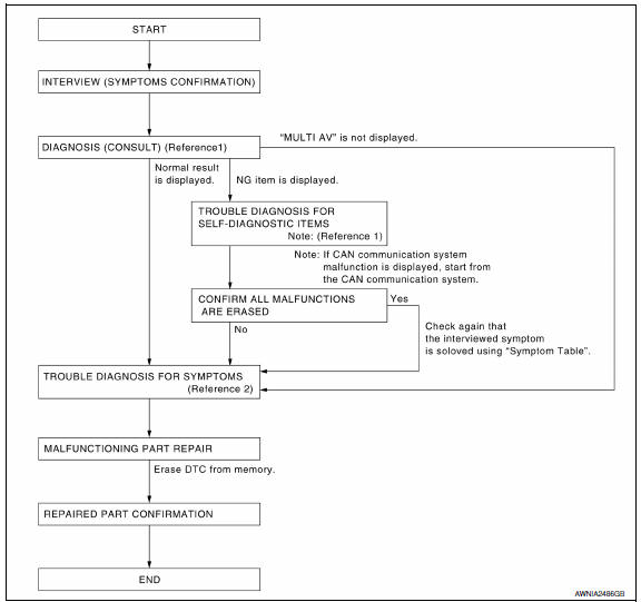
DETAILED FLOW
1.CHECK SYMPTOM
Check the malfunction symptoms by performing the following items.
- Interview the customer to obtain the malfunction information (conditions and environment when the malfunction occurred).
- Check the symptom.
2.SELF-DIAGNOSIS (CONSULT)
- Connect CONSULT and perform "SELF-DIAGNOSIS" for "MULTI AV". NOTE: Skip to step 4 of the diagnosis procedure if "MULTI AV" is not displayed.
- Check if any DTC No. is displayed in the self-diagnosis results.
3.CHECK SELF-DIAGNOSIS RESULTS (CONSULT)
- Check the DTC No. indicated in the self-diagnosis results.
- Perform the relevant diagnosis referring to the DTC No. list. Refer to AV-607, "DTC Index".
NOTE: Start with the diagnosis for the CAN communication system if "CAN COMM CIRCUIT [U1000] or CONTROL UNIT (CAN) [U1010]" is displayed.
4.PERFORM DIAGNOSIS BY SYMPTOM
Perform the relevant diagnosis referring to the diagnosis chart by symptom.
5.REPAIR OR REPLACE MALFUNCTIONING PARTS
Repair or replace the identified malfunctioning parts.
NOTE: Erase the stored self-diagnosis results after repairing or replacing the relevant components if any DTC No. has been indicated in the self-diagnosis results.
6.CHECK AFTER REPAIR
- Perform self-diagnosis for "MULTI AV" with CONSULT after repairing or replacing the malfunctioning parts.
- Check if any DTC No. is displayed in the self-diagnosis results.
7.FINAL CHECK
Perform the operation check to confirm that the malfunction symptom is solved or that any other symptoms are present.
 Basic inspection
...
 Inspection and adjustment
ADDITIONAL SERVICE WHEN REPLACING CONTROL UNIT
ADDITIONAL SERVICE WHEN REPLACING CONTROL UNIT : Description
BEFORE REPLACEMENT
When replacing AV control unit, save current vehicle specification wit ...
Other materials:
Spark plugs
Replacing spark plugs
Iridium-tipped spark plugs
It is not necessary to replace iridium-tipped A
spark plugs as frequently as conventional type
spark plugs because they last much longer. Follow
the maintenance log shown in the "Maintenance
and schedules" section of this manual. Do
not ser ...
Aluminum alloy wheels
Wash the wheels regularly with a sponge dampened
in a mild soap solution, especially during
winter months in areas where road salt is used. If
not removed, road salt can discolor the wheels.
CAUTION
Follow the directions below to avoid
staining or discoloring the wheels:
Do not use a clean ...
Precaution
PRECAUTIONS
Precaution for Supplemental Restraint System (SRS) "AIR BAG" and
"SEAT BELT PRE-TENSIONER"
The Supplemental Restraint System such as "AIR BAG" and "SEAT BELT
PRE-TENSIONER", used along with a front seat belt, helps to reduce the risk
or severity of injury to the driver and front ...
Nissan Maxima Owners Manual
- Illustrated table of contents
- Safety-Seats, seat belts and supplemental restraint system
- Instruments and controls
- Pre-driving checks and adjustments
- Monitor, climate, audio, phone and voice recognition systems
- Starting and driving
- In case of emergency
- Appearance and care
- Do-it-yourself
- Maintenance and schedules
- Technical and consumer information
Nissan Maxima Service and Repair Manual

0.0054