Nissan Maxima Service and Repair Manual: B260f engine status
Description
BCM receives the engine status signal from ECM via CAN communication.
DTC Logic
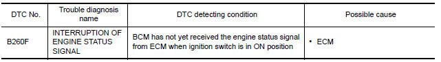
DTC DETECTION LOGIC
NOTE:
-
If DTC B260F is displayed with DTC U1000, first perform the trouble diagnosis for DTC U1000. Refer to SEC-29, "DTC Logic".
-
If DTC B260F is displayed with DTC U1010, first perform the trouble diagnosis for DTC U1010. Refer to SEC-30, "DTC Logic".
DTC CONFIRMATION PROCEDURE
1.PERFORM DTC CONFIRMATION PROCEDURE
-
Turn ignition switch ON under the following conditions.
-
CVT selector lever is in the P position.
-
Do not depress the brake pedal.
-
-
Check "Self diagnostic result" with CONSULT.
Diagnosis Procedure
1.INSPECTION START
-
Turn ignition switch ON.
-
Check "Self diagnostic result" with CONSULT.
-
Touch "ERASE".
-
Perform DTC Confirmation Procedure.
See SEC-65, "DTC Logic".
2.REPLACE ECM
-
Replace ECM.
-
Go to EC-17, "ADDITIONAL SERVICE WHEN REPLACING CONTROL UNIT : Description".
-
Inspection End.
 B2608 starter relay
Description
Located in IPDM E/R, it runs the starter motor. The
starter relay is turned ON by the BCM when the ignition
switch is in START position. IPDM E/R transmits the starter relay ON signal ...
 B26e1 no reception of engine status signal
Description
BCM receives the engine status signal from ECM via CAN
communication.
DTC Logic
DTC DETECTION LOGIC
NOTE:
If DTC B26E1 is displayed with DTC
U1000, first perform the troubl ...
Other materials:
ECU diagnosis information
ECM
Reference Value
VALUES ON THE DIAGNOSIS TOOL
NOTE:
The following table includes information (items) inapplicable
to this vehicle. For information (items) applicable
to this vehicle, refer to CONSULT display items.
Numerical values in the following table are reference v ...
Wiring diagram
POWER DISTRIBUTION SYSTEM
Wiring Diagram
...
Power seat switch ground circuit
Diagnosis Procedure
1. CHECK POWER SEAT SWITCH LH GROUND CIRCUIT
Turn ignition switch OFF.
Disconnect power seat switch LH.
Check continuity between power seat switch LH connector and
ground.
...
Nissan Maxima Owners Manual
- Illustrated table of contents
- Safety-Seats, seat belts and supplemental restraint system
- Instruments and controls
- Pre-driving checks and adjustments
- Monitor, climate, audio, phone and voice recognition systems
- Starting and driving
- In case of emergency
- Appearance and care
- Do-it-yourself
- Maintenance and schedules
- Technical and consumer information
Nissan Maxima Service and Repair Manual

0.0059