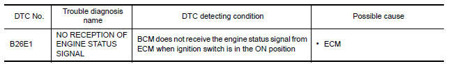
Nissan Maxima Service and Repair Manual: B26e1 no reception of engine status signal
Description
BCM receives the engine status signal from ECM via CAN communication.
DTC Logic
DTC DETECTION LOGIC
NOTE:
-
If DTC B26E1 is displayed with DTC U1000, first perform the trouble diagnosis for DTC U1000. Refer to SEC-29, "DTC Logic".
-
If DTC B26E1 is displayed with DTC U1010, first perform the trouble diagnosis for DTC U1010. Refer to SEC-30, "DTC Logic".
DTC CONFIRMATION PROCEDURE
1.PERFORM DTC CONFIRMATION PROCEDURE
-
Turn ignition switch ON under the following conditions.
-
CVT selector lever is in the P or N position.
-
Do not depress the brake pedal.
-
-
Check "Self diagnostic result" with CONSULT.
Diagnosis Procedure
1.INSPECTION START
-
Turn ignition switch ON.
-
Check "Self diagnostic result" with CONSULT.
-
Touch "ERASE".
-
Perform DTC Confirmation Procedure.
See SEC-66, "DTC Logic".
2.REPLACE ECM
-
Replace ECM.
-
Go to EC-17, "ADDITIONAL SERVICE WHEN REPLACING CONTROL UNIT : Description".
Inspection End.
 B260f engine status
Description
BCM receives the engine status signal from ECM via CAN
communication.
DTC Logic
DTC DETECTION LOGIC
NOTE:
If DTC B260F is displayed with DTC
U1000, first perform the troubl ...
 B2617 starter relay circuit
Description
Located in IPDM E/R, it runs the starter motor. The
starter relay is turned ON by the BCM when the ignition
switch is in START position. IPDM E/R transmits the starter relay ON signal ...
Other materials:
Adjustable head restraint/headrest components
1. Removable head restraint/headrest
2. Multiple notches
3. Lock knob
4. Stalks
Non-adjustable head restraint/headrest components
1. Removable head restraint/headrest
2. Single notch
3. Lock knob
4. Stalks ...
U1218 AV control unit
DTC Logic
U1219 AV CONTROL UNIT
DTC Logic
U121A AV CONTROL UNIT
DTC Logic
U121B AV CONTROL UNIT
DTC Logic
U121C AV CONTROL UNIT
DTC Logic
...
Rear bumper
Exploded View
Rear bumper supports (RH/LH)
Rear bumper reinforcement
Rear energy absorber
Side bracket (RH/LH)
Rear bumper fascia
Removal and Installation
REMOVAL
Remove trunk floor carpet, side finishers, and rear finisher.
Refer to EXT-31, "Exploded View".
Remove the r ...
Nissan Maxima Owners Manual
- Illustrated table of contents
- Safety-Seats, seat belts and supplemental restraint system
- Instruments and controls
- Pre-driving checks and adjustments
- Monitor, climate, audio, phone and voice recognition systems
- Starting and driving
- In case of emergency
- Appearance and care
- Do-it-yourself
- Maintenance and schedules
- Technical and consumer information
Nissan Maxima Service and Repair Manual

0.0084