Nissan Maxima Service and Repair Manual: B2617 starter relay circuit
Description
Located in IPDM E/R, it runs the starter motor. The starter relay is turned ON by the BCM when the ignition switch is in START position. IPDM E/R transmits the starter relay ON signal to BCM via CAN communication.
DTC Logic
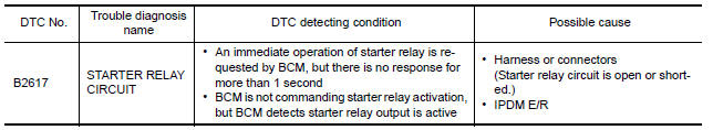
DTC DETECTION LOGIC
NOTE:
-
If DTC B2617 is displayed with DTC U1000, first perform the trouble diagnosis for DTC U1000. Refer to SEC-29, "DTC Logic".
-
If DTC B2617 is displayed with DTC U1010, first perform the trouble diagnosis for DTC U1010. Refer to SEC-30, "DTC Logic".
-
If DTC B2617 is displayed with DTC B210E, first perform the trouble diagnosis for DTC B210E. Refer to SEC-67, "DTC Logic".
DTC CONFIRMATION PROCEDURE
1.PERFORM DTC CONFIRMATION PROCEDURE
-
Turn ignition switch ON under the following conditions and wait for at least 1 second.
-
CVT selector lever is in the P position.
-
Do not depress the brake pedal.
-
-
Check "Self diagnostic result" with CONSULT.
Diagnosis Procedure
Regarding Wiring Diagram information, refer to SEC-147, "Wiring Diagram" or SEC-128, "Wiring Diagram".
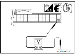
1.CHECK STARTER RELAY
-
Turn ignition switch ON.
-
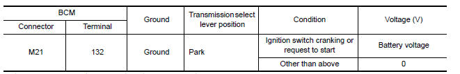
Check voltage between BCM harness connector M21 terminal 132 and ground under the following condition.
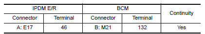
2.CHECK STARTER RELAY CIRCUIT
-
Turn ignition switch OFF.
-
Disconnect BCM harness connector and IPDM E/R harness connector.
-
Check continuity between IPDM E/R harness connector E17 (A) terminal 46 and BCM harness connector M21 (B) terminal 132.
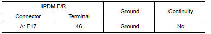
4. Check continuity between IPDM E/R harness connector E17 (A) terminal 46 and ground.
3.CHECK INTERMITTENT INCIDENT
Refer to GI-41, "Intermittent Incident".
Inspection End.
 B26e1 no reception of engine status signal
Description
BCM receives the engine status signal from ECM via CAN
communication.
DTC Logic
DTC DETECTION LOGIC
NOTE:
If DTC B26E1 is displayed with DTC
U1000, first perform the troubl ...
 B210b starter control relay
DTC Logic
DTC DETECTION LOGIC
NOTE:
If DTC B210B is displayed with DTC
U1000, first perform the trouble diagnosis for DTC U1000. Refer to
SEC-29, "DTC Logic".
If DTC B210B is di ...
Other materials:
Fog light switch
To turn the fog lights on, turn the headlight switch
to the position, then turn the fog
light
switch to the position.
To turn the fog lights on with the headlight switch
in the AUTO position, the headlights must be on,
then turn the fog light switch to the
position.
To turn the f ...
Steering switch
Description
When one of the steering wheel audio control switches is pushed, the
resistance in the steering wheel audio control switch circuit changes,
depending on which button is pushed.
Diagnosis Procedure
1.CHECK STEERING SWITCH RESISTANCE
Disconnect steering switch connector M88. ...
Power supply and ground circuit
CLIMATE CONTROLLED SEAT CONTROL UNIT
CLIMATE CONTROLLED SEAT CONTROL UNIT : Diagnosis Procedure
Regarding Wiring Diagram information, refer to SE-44, "Wiring Diagram".
1.CHECK FUSES
2.CHECK BATTERY POWER SUPPLY CIRCUIT
Turn ignition switch OFF.
Disconnect climate controlled seat control ...
Nissan Maxima Owners Manual
- Illustrated table of contents
- Safety-Seats, seat belts and supplemental restraint system
- Instruments and controls
- Pre-driving checks and adjustments
- Monitor, climate, audio, phone and voice recognition systems
- Starting and driving
- In case of emergency
- Appearance and care
- Do-it-yourself
- Maintenance and schedules
- Technical and consumer information
Nissan Maxima Service and Repair Manual

0.0059