Nissan Maxima Service and Repair Manual: Satellite radio antenna
Removal and Installation
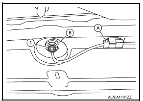
REMOVAL
- Lower the headlining at the rear. Refer to INT-33, "Exploded View".
- Disconnect the harness connector (A) from satellite radio antenna.
- Remove the satellite radio antenna nut (B) and the satellite radio antenna (1).
INSTALLATION
Installation is in the reverse order of removal.
 Satellite radio tuner
Removal and Installation
REMOVAL
Disconnect the battery negative terminal. Refer to PG-67, "Removal
and Installation (Battery)".
Remove the trunk upper finisher. Refer to INT-36, & ...
 Steering switch
Removal and Installation
REMOVAL
Remove the driver airbag module. Refer to SR-12, "Removal and
Installation".
Remove the steering wheel audio control switch screws (A).
Release t ...
Other materials:
Front combination lamp
Disassembly and Assembly
EXPLODED VIEW
Front combination lamp
Halogen bulb (low beam)
Halogen bulb socket (low beam)
Side marker lamp bulb
Side marker lamp socket
Front turn signal lamp socket
Front turn signal lamp bulb
Halogen bulb socket (high beam)
Halogen bulb (high ...
Diagnosis system (AV control unit)
Diagnosis Description
MULTIFUNCTION SWITCH AND PRESET SWITCH SELF-DIAGNOSIS FUNCTION
The ON/OFF operation (continuity) of each switch in the multifunction switch
and preset switch can be checked.
Self-Diagnosis Mode
Press the BACK switch and the
switch of the 8-direction switches with ...
AV branch line circuit
Diagnosis Procedure
1.CHECK CONNECTOR
Turn the ignition switch OFF.
Disconnect the battery cable from the negative terminal.
Check the terminals and connectors of the AV control unit for
damage, bend and loose connection (unit
side and connector side).
2.CHECK HARNESS FOR OPEN CIRC ...
Nissan Maxima Owners Manual
- Illustrated table of contents
- Safety-Seats, seat belts and supplemental restraint system
- Instruments and controls
- Pre-driving checks and adjustments
- Monitor, climate, audio, phone and voice recognition systems
- Starting and driving
- In case of emergency
- Appearance and care
- Do-it-yourself
- Maintenance and schedules
- Technical and consumer information
Nissan Maxima Service and Repair Manual

0.0065