Nissan Maxima Service and Repair Manual: Microphone signal circuit
Description
Voice signals are transmitted from the microphone to the AV control unit using the microphone signal circuits.
Diagnosis Procedure
1.CHECK HARNESS BETWEEN AV CONTROL UNIT AND MICROPHONE
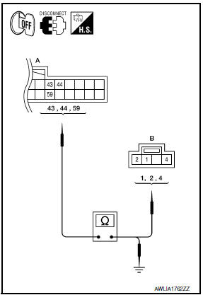
- Turn ignition switch OFF.
- Disconnect AV control unit connector and microphone connector.
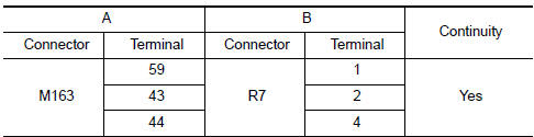
- Check continuity between AV control unit harness connector M163 (A) and microphone harness connector R7 (B).
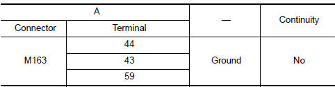
- Check continuity between AV control unit harness connector M163 (A) and ground.
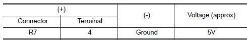
2.CHECK MICROPHONE POWER SUPPLY
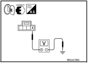
- Connect AV control unit connector and microphone connector.
- Turn ignition switch ON.
- Check voltage between microphone harness connector R7 terminal 4 and ground.
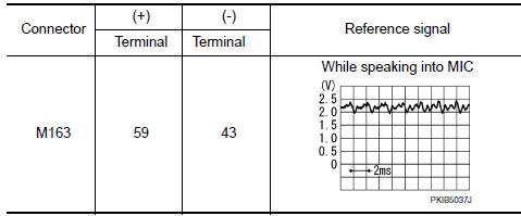
3.CHECK MICROPHONE SIGNAL
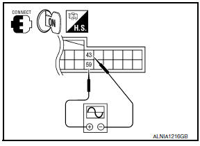
Check signal between AV control unit harness connector M163 terminals 43 and 59.
 Disk eject signal circuit
Description
The eject signal is output to AV control unit when the eject switch of A/C
and AV switch assembly is pressed.
Diagnosis Procedure
1.CHECK CONTINUITY DISK EJECT SIGNAL CIRCUIT
...
 AMP on signal circuit
Description
When the audio system is turned on, a voltage signal is supplied from the AV
control unit to the BOSE speaker
amp. When this signal is received, the BOSE speaker amp. will turn on.
D ...
Other materials:
Microphone
Removal and Installation
REMOVAL
Remove the front room/map lamp assembly. Refer to INL-84, "Removal
and Installation".
Detach the microphone connector (A).
Remove the front room/map lamp covers (1), then remove the
map lamp assembly cover (2).
Release the m ...
Cooler pipe and hose
Exploded View
Heater and cooling unit assembly
High-pressure pipe
High-pressure A/C service valve
High-pressure flexible hose
Air deflector (RH)
Junction pipe
Condenser
Liquid tank
Refrigerant pressure sensor
Condenser, liquid tank and refrigerant pressure sensor
Air ...
P0011, P0021 IVT control
DTC Logic
DTC DETECTION LOGIC
NOTE:
If DTC P0011 or P0021 is displayed with DTC P0075, P0081, first perform the
trouble diagnosis for DTC
P0075, P0081.
DTC CONFIRMATION PROCEDURE
1.PRECONDITIONING
If DTC Confirmation Procedure has been previously conducted, always perform
the follow ...
Nissan Maxima Owners Manual
- Illustrated table of contents
- Safety-Seats, seat belts and supplemental restraint system
- Instruments and controls
- Pre-driving checks and adjustments
- Monitor, climate, audio, phone and voice recognition systems
- Starting and driving
- In case of emergency
- Appearance and care
- Do-it-yourself
- Maintenance and schedules
- Technical and consumer information
Nissan Maxima Service and Repair Manual

0.0062