Nissan Maxima Service and Repair Manual: AMP on signal circuit
Description
When the audio system is turned on, a voltage signal is supplied from the AV control unit to the BOSE speaker amp. When this signal is received, the BOSE speaker amp. will turn on.
Diagnosis Procedure
1.CHECK AMP ON SIGNAL (BOSE SPEAKER AMP)
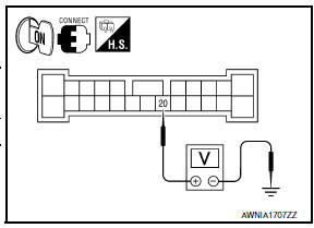
- Turn audio system ON.
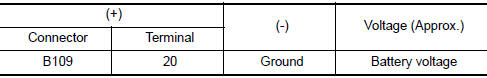
- Check voltage between BOSE speaker amp. harness connector B109 terminal 20 and ground.
2.CHECK AMP ON SIGNAL (AV CONTROL UNIT)
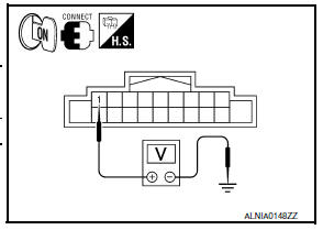
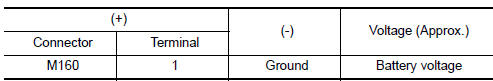
Check voltage between AV control unit harness connector M160 terminal 1 and ground
 Microphone signal circuit
Description
Voice signals are transmitted from the microphone to the AV control unit
using the microphone signal circuits.
Diagnosis Procedure
1.CHECK HARNESS BETWEEN AV CONTROL UNIT AND MICROPHO ...
 Front door speaker
Description
The AV control unit sends audio signals to the BOSE speaker amp. The BOSE
speaker amp. amplifies the
audio signals before sending them to the front door speakers using the audio
sig ...
Other materials:
Diagnosis system (HVAC)
CONSULT Function
CONSULT can display each diagnosis item using the diagnosis test modes as
shown.
CONSULT application items
SELF-DIAGNOSTIC RESULT
Display Item List
*: Perform self-diagnosis under sunshine. When performing indoors, aim a
light (more than 60 W) at sunload sensor, ...
Inspection and adjustment
ADDITIONAL SERVICE WHEN REPLACING CONTROL UNIT
ADDITIONAL SERVICE WHEN REPLACING CONTROL UNIT : Description
Initialization of system should be conducted after the following conditions.
When the sunroof motor or sunshade motor is changed.
When the sunroof of sunshade does not operate normally ...
P1612 chain of ECM-IMMU
Description
BCM performs the ID verification with ECM that allows the
engine to start. Start the engine if the ID is OK.
ECM prevents the engine from starting if the ID is not registered. BCM starts
the communication with ECM if
ignition switch is turned ON.
DTC Logic
DTC DETECTION LOGIC ...
Nissan Maxima Owners Manual
- Illustrated table of contents
- Safety-Seats, seat belts and supplemental restraint system
- Instruments and controls
- Pre-driving checks and adjustments
- Monitor, climate, audio, phone and voice recognition systems
- Starting and driving
- In case of emergency
- Appearance and care
- Do-it-yourself
- Maintenance and schedules
- Technical and consumer information
Nissan Maxima Service and Repair Manual

0.006