Nissan Maxima Service and Repair Manual: Front door speaker
Description
The AV control unit sends audio signals to the BOSE speaker amp. The BOSE speaker amp. amplifies the audio signals before sending them to the front door speakers using the audio signal circuits.
Diagnosis Procedure
1.CONNECTOR CHECK
Check the AV control unit, BOSE speaker amp. and speaker connectors for the following:
- Proper connection
- Damage
- Disconnected or loose terminals
2.HARNESS CHECK

- Disconnect BOSE speaker amp. connector B109 and suspect speaker connector.
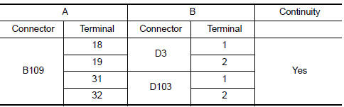
- Check continuity between BOSE speaker amp. harness connector B109 (A) and suspect speaker harness connector (B).
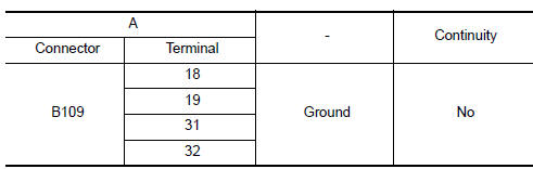
- Check continuity between BOSE speaker amp. harness connector B109 (A) and ground.
3.FRONT DOOR SPEAKER SIGNAL CHECK
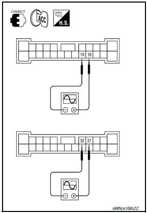
- Connect BOSE speaker amp. connector B109 and suspect speaker connector.
- Turn ignition switch to ACC.
- Push POWER switch.
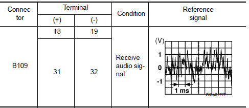
- Check the signal between BOSE speaker amp. harness connector B109 terminals with CONSULT or oscilloscope
4.HARNESS CHECK
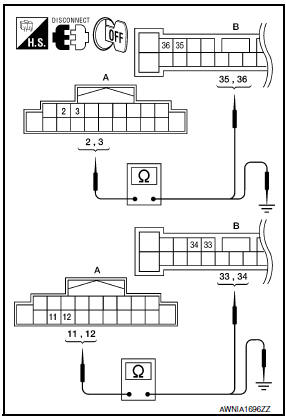
- Disconnect AV control unit connector M160 and BOSE speaker amp. connector B109.
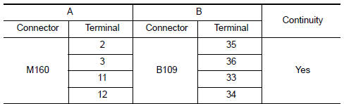
- Check continuity between AV control unit harness connector M160 (A) and BOSE speaker amp. harness connector B109 (B).
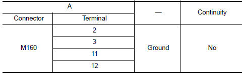
- Check continuity between AV control unit harness connector M160 (A) and ground.
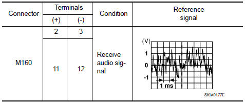
5.FRONT DOOR SPEAKER SIGNAL CHECK
- Connect AV control unit connector and BOSE speaker amp.
connector.
- Turn ignition switch ACC.
- Push POWER switch.
- Check the signal between AV control unit harness connector terminals with CONSULT or oscilloscope.
 AMP on signal circuit
Description
When the audio system is turned on, a voltage signal is supplied from the AV
control unit to the BOSE speaker
amp. When this signal is received, the BOSE speaker amp. will turn on.
D ...
 Tweeter
Description
The AV control unit sends audio signals to the BOSE speaker amp. The BOSE
speaker amp. amplifies the
audio signals before sending them to the tweeters using the audio signal
circuit ...
Other materials:
Precaution
Precaution for Supplemental Restraint System (SRS) "AIR BAG" and
"SEAT BELTPRE-TENSIONER"
The Supplemental Restraint System such as “AIR BAG” and “SEAT BELT
PRE-TENSIONER”, used alongwith a front seat belt, helps to reduce the risk
or severity of injury to the driver and front passeng ...
Tire inflation pressure
Check the tire pressures (including the
spare) often and always prior to long distance
trips. The recommended tire pressure
specifications are shown on the
F.M.V.S.S./C.M.V.S.S. certification label
or the Tire and Loading Information label
under the Cold Tire Pressure heading.
The Tire and ...
P0031, P0032, P0051, P0052 A/F sensor 1 heater
Description
SYSTEM DESCRIPTION
The ECM performs ON/OFF duty control of the A/F sensor 1 heater corresponding
to the engine operating
condition to keep the temperature of A/F sensor 1 element within the specified
range.
DTC Logic
DTC DETECTION LOGIC
DTC CONFIRMATION PROCEDURE
1.PR ...
Nissan Maxima Owners Manual
- Illustrated table of contents
- Safety-Seats, seat belts and supplemental restraint system
- Instruments and controls
- Pre-driving checks and adjustments
- Monitor, climate, audio, phone and voice recognition systems
- Starting and driving
- In case of emergency
- Appearance and care
- Do-it-yourself
- Maintenance and schedules
- Technical and consumer information
Nissan Maxima Service and Repair Manual

0.006