Nissan Maxima Service and Repair Manual: Tweeter
Description
The AV control unit sends audio signals to the BOSE speaker amp. The BOSE speaker amp. amplifies the audio signals before sending them to the tweeters using the audio signal circuits.
Diagnosis Procedure
1.CONNECTOR CHECK
Check the AV control unit, BOSE speaker amp. and speaker connectors for the following:
- Proper connection
- Damage
- Disconnected or loose terminals
2.HARNESS CHECK
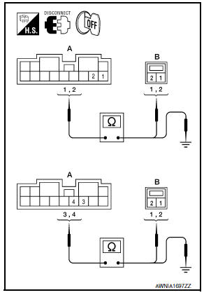
- Disconnect BOSE speaker amp. connector B110 and suspect tweeter connector.
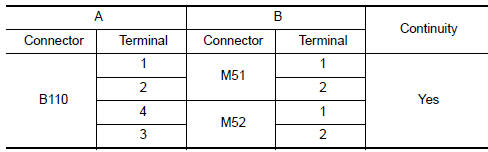
- Check continuity between BOSE speaker amp. harness connector B110 (A) and suspect tweeter harness connector (B).
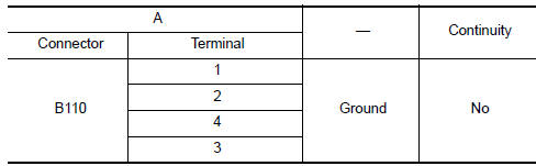
- Check continuity between BOSE speaker amp. harness connector B110 (A) and ground.
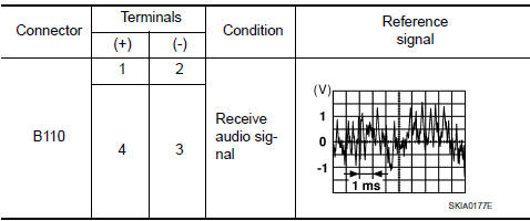
3.TWEETER SIGNAL CHECK
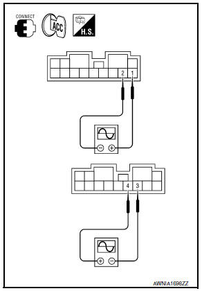
- Connect BOSE speaker amp. connector B110 and suspect tweeter connector.
- Turn ignition switch to ACC.
- Push POWER switch.
- Check the signal between BOSE speaker amp. harness connector B110 terminals with CONSULT or oscilloscope.
4.HARNESS CHECK
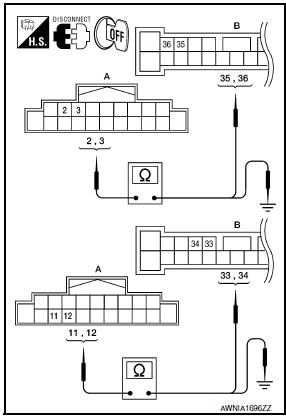
- Disconnect AV control unit connector M160 and BOSE speaker amp. connector B109.
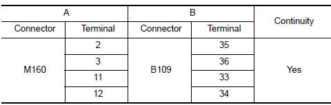
- Check continuity between AV control unit harness connector M160 (A) and BOSE speaker amp. harness connector B109 (B).
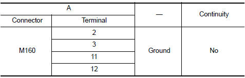
- Check continuity between AV control unit harness connector M160 (A) and ground.
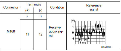
5.TWEETER SIGNAL CHECK
- Connect AV control unit connector and BOSE speaker amp.
connector.
- Turn ignition switch ACC.
- Push POWER switch.
- Check the signal between AV control unit harness connector terminals with CONSULT or oscilloscope.
 Front door speaker
Description
The AV control unit sends audio signals to the BOSE speaker amp. The BOSE
speaker amp. amplifies the
audio signals before sending them to the front door speakers using the audio
sig ...
 Center speaker
Description
The AV control unit sends audio signals to the BOSE speaker amp. The BOSE
speaker amp. amplifies the
audio signals before sending them to the center speaker using the audio signal
c ...
Other materials:
Air bags, seat belts and child restraints
Top tether strap anchor
Rear head restraints/headrests
Rear seat belts
Roof-mounted curtain side-impact and
rollover supplemental air bag
Front seat-mounted side-impact
supplemental air bags
Front head restraints/headrests
Front seat belt with pretensioner(s) and
shoulder he ...
Shifting
After starting the engine, fully depress the brake
pedal and move the shift lever from P (Park) to
any of the desired shift positions.
WARNING
Apply the parking brake if the shift lever is
in any position while the engine is not
running. Failure to do so could cause the
vehicle to move unexpe ...
Diagnosis system (BCM)
COMMON ITEM
COMMON ITEM : CONSULT Function (BCM - COMMON ITEM)
APPLICATION ITEM
CONSULT performs the following functions via CAN communication with BCM.
SYSTEM APPLICATION
BCM can perform the following functions.
BCM
BCM : CONSULT Function (BCM - BCM)
ECU IDENTIFICATION
The BCM part ...
Nissan Maxima Owners Manual
- Illustrated table of contents
- Safety-Seats, seat belts and supplemental restraint system
- Instruments and controls
- Pre-driving checks and adjustments
- Monitor, climate, audio, phone and voice recognition systems
- Starting and driving
- In case of emergency
- Appearance and care
- Do-it-yourself
- Maintenance and schedules
- Technical and consumer information
Nissan Maxima Service and Repair Manual

0.0105