Nissan Maxima Service and Repair Manual: Center speaker
Description
The AV control unit sends audio signals to the BOSE speaker amp. The BOSE speaker amp. amplifies the audio signals before sending them to the center speaker using the audio signal circuits.
Diagnosis Procedure
1.CONNECTOR CHECK
Check the AV control unit, BOSE speaker amp. and speaker connectors for the following:
- Proper connection
- Damage
- Disconnected or loose terminals
2.HARNESS CHECK
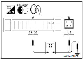
- Disconnect BOSE speaker amp. connector B109 and center speaker connector M130.
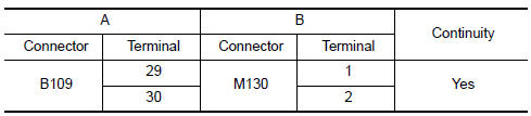
- Check continuity between BOSE speaker amp. harness connector B109 (A) and center speaker harness connector M130 (B).
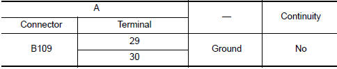
- Check continuity between BOSE speaker amp. harness connector B109 (A) and ground.
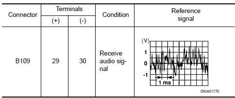
3.CENTER SPEAKER SIGNAL CHECK
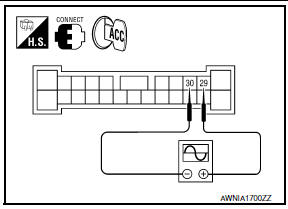
- Connect BOSE speaker amp. connector B109 and center speaker connector.
- Turn ignition switch to ACC.
- Push POWER switch.
- Check the signal between BOSE speaker amp. harness connector B109 terminals with CONSULT or oscilloscope.
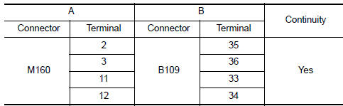
4.HARNESS CHECK

- Disconnect AV control unit connector M160 and BOSE speaker amp. connector B109.
- Check continuity between AV control unit harness connector M160 (A) and BOSE speaker amp. harness connector B109 (B).
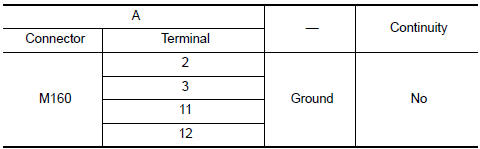
- Check continuity between AV control unit harness connector M160 (A) and ground.
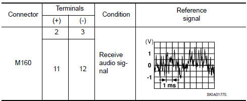
5.CENTER SPEAKER SIGNAL CHECK
- Connect AV control unit connector and BOSE speaker amp.
connector.
- Turn ignition switch ACC.
- Push POWER switch.
- Check the signal between AV control unit harness connector terminals with CONSULT or oscilloscope.
 Tweeter
Description
The AV control unit sends audio signals to the BOSE speaker amp. The BOSE
speaker amp. amplifies the
audio signals before sending them to the tweeters using the audio signal
circuit ...
 Rear door speaker
Description
The AV control unit sends audio signals to the BOSE speaker amp. The BOSE
speaker amp. amplifies the
audio signals before sending them to the rear door speakers using the audio
sign ...
Other materials:
In-vehicle sensor
Removal and Installation
REMOVAL
Remove the instrument lower panel LH. Refer to IP-19, "Removal and
Installation".
Remove the in-vehicle sensor screw and the in-vehicle sensor.
INSTALLATION
Installation is in the reverse order of removal.
CAUTION:
Make sure that the asp ...
Power seat switch ground circuit
Diagnosis Procedure
1. CHECK POWER SEAT SWITCH LH GROUND CIRCUIT
Turn ignition switch OFF.
Disconnect power seat switch LH.
Check continuity between power seat switch LH connector and
ground.
...
Composite image signal circuit
Description
AV control unit transmits the playback DVD image signal and AUX image signal
to the display unit.
Diagnosis Procedure
1.CHECK CONTINUITY COMPOSITE IMAGE SIGNAL CIRCUIT
Turn ignition switch OFF.
Disconnect AV control unit connector M163 and display unit
connector
M142 ...
Nissan Maxima Owners Manual
- Illustrated table of contents
- Safety-Seats, seat belts and supplemental restraint system
- Instruments and controls
- Pre-driving checks and adjustments
- Monitor, climate, audio, phone and voice recognition systems
- Starting and driving
- In case of emergency
- Appearance and care
- Do-it-yourself
- Maintenance and schedules
- Technical and consumer information
Nissan Maxima Service and Repair Manual

0.0085