Nissan Maxima Service and Repair Manual: Front fender
Exploded View
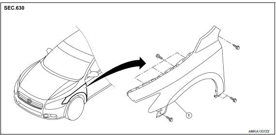
- Front fender
Removal and Installation
REMOVAL
- Remove the front combination lamp. Refer to EXL-154, "Removal and Installation".
- Remove the fender protector. Refer to EXT-24, "Removal and Installation".
- Remove cowl top side trim cover. EXT-21, "Removal and Installation"
- Remove the bolts and the front fender.
CAUTION:
- Use shop cloths to protect the body from being damaged during removal and installation.
- Use care when removing the front fender. The front fender baffle foam adheres the front fender to the body side outer. Carefully release the baffle foam or damage to the front fender may occur.
INSTALLATION
Installation is in the reverse order of removal.
CAUTION:
- After installation apply touch up paint (body color) to the head of front fender bolts.
- After installation, adjust the following components as necessary:
- Hood assembly: Refer to DLK-203, "HOOD ASSEMBLY : Adjustment".
- Front door: Refer to DLK-215, "FRONT DOOR : Adjustment".
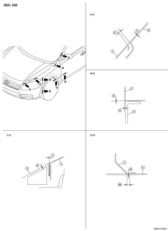
Adjustment
- Front fender
- Front fascia
- Body side outer
- Front door assembly
- Remove the fender protector. Refer to EXT-24, "Removal and Installation".
- Loosen the front fender bolts and screws.
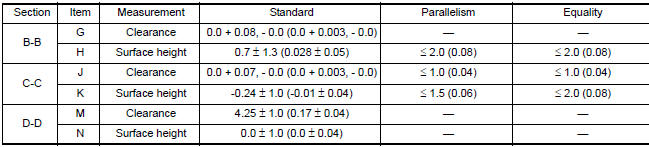
- Adjust the clearance (M) and surface height (N) between the front fender and the front door.
- Tighten the rear upper and lower front fender bolts.
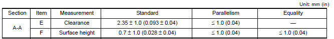
- Adjust the clearance (E) and surface height (F) between the front fender and the body side outer.
- Tighten the inner front fender bolts.
- Adjust the clearance (J) and the surface height (K) between the top of the front fender and the top of the front fascia.
- Adjust the clearance (G) and surface height (H) between the side of the front fender and the side of the front fascia.
- Tighten the front fender to front fascia and bracket screws.
- Apply touch-up paint (body color) to the head of the front fender bolts.
- Install the fender protector. Refer to EXT-24, "Removal and Installation".
- Install the inner fender bolt cover.
 Radiator core support
Exploded View
Radiator core support
Bolts
Removal and Installation
REMOVAL
Remove front bumper. Refer to EXT-16, "Removal and Installation".
Remove front combinat ...
 Door
Door
FRONT DOOR
FRONT DOOR : Exploded View
Front door panel
Front door check link
Front door lower hinge
Front lower hinge
Grease
FRONT DOOR : Removal and Installation
CAUTION: ...
Other materials:
Memory function does not operate
Component Function Check
Symptom
Memory function does not operate normally.
The setting is not maintained. (It returns to the initial
condition.)
1.CHECK OPERATION
Set temperature control dial to 32C (90F).
Press the OFF switch.
Turn the ignition switch OFF.
Turn the ignition ...
Power consumption control system
System Diagram
System Description
OUTLINE
IPDM E/R incorporates a power consumption control function that
reduces the power consumption according
to the vehicle status.
IPDM E/R changes its status (control mode) with the sleep wake up
signal received from BCM via CAN communicati ...
Audio system
System Diagram
System Description
AUDIO SYSTEM
The audio system consists of the following components
Audio unit
Display unit
Bluetooth control unit
Window antenna
BOSE speaker amp.
Steering wheel audio control switches
Front door speakers
Tweeters
Center speaker
Rear door ...
Nissan Maxima Owners Manual
- Illustrated table of contents
- Safety-Seats, seat belts and supplemental restraint system
- Instruments and controls
- Pre-driving checks and adjustments
- Monitor, climate, audio, phone and voice recognition systems
- Starting and driving
- In case of emergency
- Appearance and care
- Do-it-yourself
- Maintenance and schedules
- Technical and consumer information
Nissan Maxima Service and Repair Manual

0.0058