Nissan Maxima Service and Repair Manual: Parking lamp circuit
Description
The IPDM E/R (intelligent power distribution module engine room) controls the tail lamp relay based on inputs from the BCM over the CAN communication lines. When the tail lamp relay is energized, power flows through fuses 46 and 47, located in the IPDM E/R. Power then flows to the front and rear combination lamps, license plate lamps.
Component Function Check
1.CHECK PARKING LAMP OPERATION
WITHOUT CONSULT
- Activate IPDM E/R auto active test. Refer to PCS-11, "Diagnosis Description".
- Check that the parking lamp is turned ON.
CONSULT
- Select "EXTERNAL LAMPS" of IPDM E/R active test item.
- While operating the test item, check that the parking lamp is turned ON.
TAIL : Parking lamp ON
OFF : Parking lamp OFF
Diagnosis Procedure
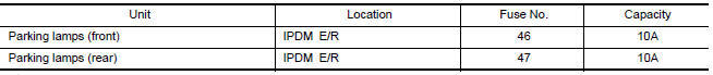
1.CHECK PARKING LAMP FUSES
- Turn the ignition switch OFF.
- Check that the following fuses are not open.
2.CHECK TAIL LAMP RELAY OUTPUT (VOLTAGE)
CONSULT
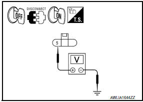
- Turn the ignition switch OFF.
- Disconnect the front and rear combination lamp connectors.
- Turn the ignition switch ON.
- Select "EXTERNAL LAMPS" of IPDM E/R active test item.
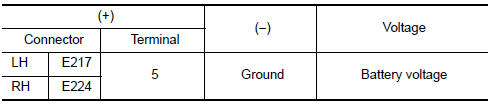
- With EXTERNAL LAMPS ON, check the voltage between the front combination lamp connector and ground.
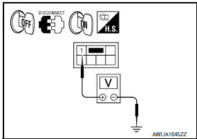
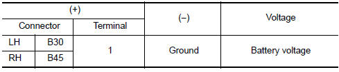
- With EXTERNAL LAMPS ON, check the voltage between the rear combination lamp connector and ground.
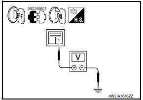
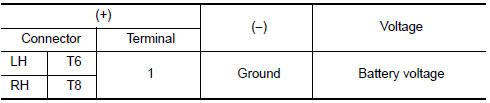
- With EXTERNAL LAMPS ON, check the voltage between the license plate lamp connector and ground.
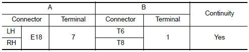
3.CHECK PARKING LAMP CIRCUIT (OPEN)
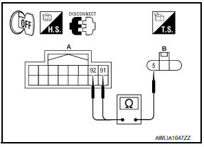
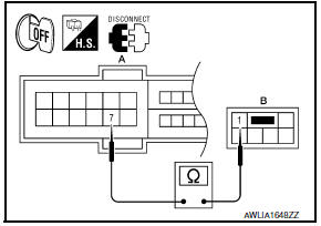
- Turn the ignition switch OFF.
- Disconnect IPDM E/R connector E201.
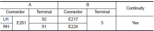
- Check continuity between the IPDM E/R harness connector (A) and the front combination lamp harness connector (B).
- Check continuity between the IPDM E/R harness connector (A) and the rear combination lamp harness connector (B).
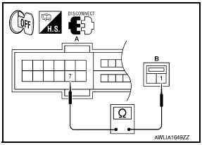
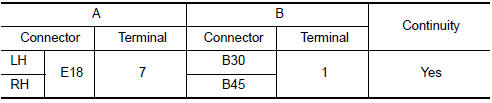
- Check continuity between the IPDM E/R harness connector (A) and the license plate lamp harness connector (B).
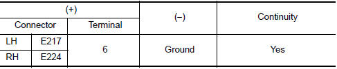
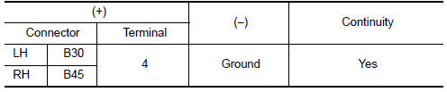
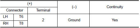
4.CHECK PARKING LAMP GROUND CIRCUIT
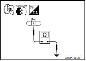
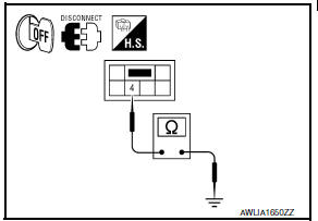
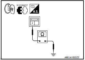
- Check continuity between the front combination lamp harness connector terminal and ground.
- Check continuity between the rear combination lamp harness connector terminal and ground.
- Check continuity between the license plate lamp harness connector terminal and ground.
 Front fog lamp circuit
Description
The IPDM E/R (intelligent power distribution module engine room) controls the
front fog lamp relay based on inputs from the BCM over the CAN communication
lines. When the front fog la ...
 Turn signal lamp circuit
Description
The BCM monitors inputs from the combination switch to determine when to
activate the turn signals. The BCM outputs voltage direction to the left and
right turn signals during turn si ...
Other materials:
ABS warning lamp
Description
Component Function Check
1.CHECK ABS WARNING LAMP OPERATION
Check that the lamp illuminates for approximately 2 seconds after the
ignition switch is turned ON.
Diagnosis Procedure
1.CHECK SELF-DIAGNOSIS
Perform ABS actuator and electric unit (control unit) self-diagnosis.
2. ...
Aux image signal circuit
Description
Transmits the image signal of AUX device from auxiliary input jacks to
AV control unit.
AV control unit transmits the image signal that is input to the
display unit.
Diagnosis Procedure
1.CHECK CONTINUITY AUX IMAGE SIGNAL CIRCUIT
Turn ignition switch OFF.
Disconnect ...
Front coil spring and strut
Removal and Insallation
REMOVAL
Remove front wheel and tire using power tool. Refer to WT-60,
"Adjustment".
Remove the wheel sensor harness from the front coil spring and
strut. Refer to BRC-102, "Removal and Installation - Front Wheel Sensor".
Remove the brake hose lock plate.
Remo ...
Nissan Maxima Owners Manual
- Illustrated table of contents
- Safety-Seats, seat belts and supplemental restraint system
- Instruments and controls
- Pre-driving checks and adjustments
- Monitor, climate, audio, phone and voice recognition systems
- Starting and driving
- In case of emergency
- Appearance and care
- Do-it-yourself
- Maintenance and schedules
- Technical and consumer information
Nissan Maxima Service and Repair Manual

0.0064