Nissan Maxima Service and Repair Manual: Turn signal lamp circuit
Description
The BCM monitors inputs from the combination switch to determine when to activate the turn signals. The BCM outputs voltage direction to the left and right turn signals during turn signal operation or both during hazard warning operation. The BCM sends a turn signal indicator request to the combination meter via the CAN communication lines.
The BCM performs the fast flasher operation (fail-safe) if any bulb or harness of the turn signal lamp circuit is open.
NOTE: Turn signal lamp blinks at normal speed when using the hazard warning lamp.
Component Function Check
1.CHECK TURN SIGNAL LAMP
CONSULT
- Select "FLASHER" of BCM (FLASHER) active test item.
- While operating the test item, check that the turn signal lamp blinks.
LH : Turn signal lamp LH blinking
RH : Turn signal lamp RH blinking
OFF : The turn signal lamp OFF
Diagnosis Procedure
1.CHECK TURN SIGNAL LAMP BULB
Check the applicable lamp bulb to be sure the proper bulb standard is in use and the bulb is not open.
2.CHECK TURN SIGNAL LAMP OUTPUT VOLTAGE
- Turn the ignition switch OFF.
- Disconnect front combination lamp connector, door mirror connector (if equipped with turn signal in mirror) and rear combination lamp connector.
- Turn the ignition switch ON.
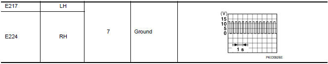
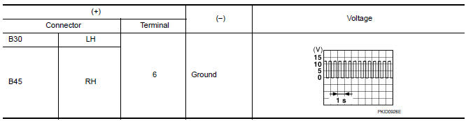
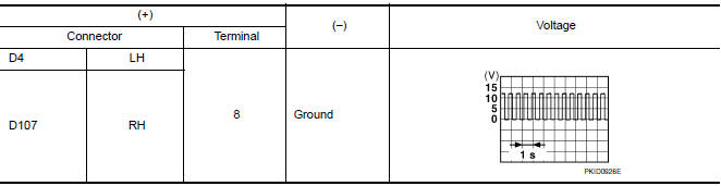
- With turn signal switch operating, check the voltage between the front combination lamp harness connector and ground.
- With turn signal switch operating, check the voltage between the rear combination lamp harness connector and ground.
- With turn signal switch operating, check the voltage between the door mirror (if equipped with turn signals in the mirrors) harness connector and ground.

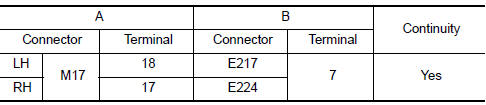
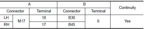
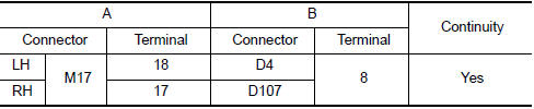
3.CHECK TURN SIGNAL LAMP CIRCUIT FOR OPEN
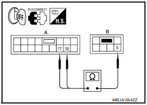
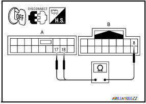
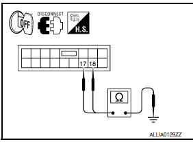
- Turn ignition switch OFF.
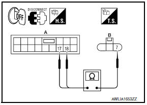
- Disconnect BCM connector M17.
- Check continuity between the BCM harness connector (A) and the front combination lamp connector (B).
- Check continuity between the BCM harness connector (A) and the rear combination lamp harness connector (B)
- Check continuity between the BCM harness connector (A) and the door mirror connector (B) (if equipped with turn signal in mirror).
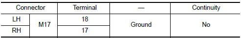
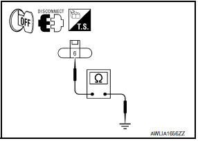
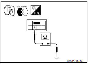
4.CHECK TURN SIGNAL LAMP SHORT CIRCUIT
Check continuity between the BCM harness connector and ground.
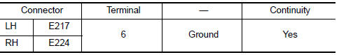
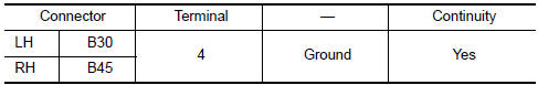
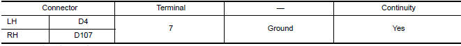
5.CHECK TURN SIGNAL LAMP GROUND CIRCUIT
- Turn ignition switch OFF.
- Check continuity between the front combination lamp and ground.
- Check continuity between the rear combination lamp and ground.
- Check continuity between the door mirror and ground (if equipped with turn signal in mirror).
 Parking lamp circuit
Description
The IPDM E/R (intelligent power distribution module engine room) controls the
tail lamp relay based on inputs from the BCM over the CAN communication
lines. When the tail lamp relay i ...
 Optical sensor
Description
The optical sensor converts the outside brightness (lux) to voltage and
transmits the optical sensor signal to the BCM.
Component Function Check
1.CHECK OPTICAL SENSOR SIGNAL BY CONSU ...
Other materials:
The oil pressure warning lamp does not turn off
Description
The oil pressure warning lamp remains illuminated while
the engine is running (normal oil pressure).
Diagnosis Procedure
Regarding Wiring Diagram information, refer to MWI-87,
"Wiring Diagram".
1.CHECK OIL PRESSURE WARNING LAMP
Perform IPDM E/R auto active test. Refer to PCS-11, ...
ABS warning lamp
Description
Component Function Check
1.CHECK ABS WARNING LAMP OPERATION
Check that the lamp illuminates for approximately 2 seconds after the
ignition switch is turned ON.
Diagnosis Procedure
1.CHECK SELF-DIAGNOSIS
Perform ABS actuator and electric unit (control unit) self-diagnosis.
2. ...
Unit removal and installation
FRONT SUSPENSION ASSEMBLY
Exploded View
Front stabilizer
Stabilizer clamp
Stabilizer bushing
Stabilizer connecting rod
Front mount bracket
Rear mount bracket
Member insulator
Member pin stay
Transverse link
Steering stopper bracket
Stopper bolt cap
Steering stopp ...
Nissan Maxima Owners Manual
- Illustrated table of contents
- Safety-Seats, seat belts and supplemental restraint system
- Instruments and controls
- Pre-driving checks and adjustments
- Monitor, climate, audio, phone and voice recognition systems
- Starting and driving
- In case of emergency
- Appearance and care
- Do-it-yourself
- Maintenance and schedules
- Technical and consumer information
Nissan Maxima Service and Repair Manual

0.0073