
Nissan Maxima Service and Repair Manual: Sunroof system
System Diagram
SUNROOF
System Description
DESCRIPTION
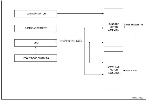
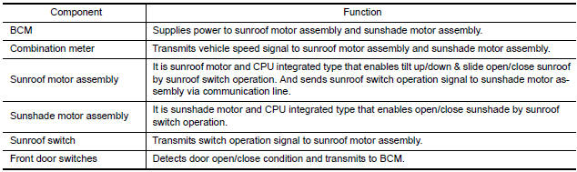
- Sunroof motor assembly and sunshade motor assembly operate with the power supplied from BCM while ignition switch is ON or retained power is operating.
- Sunroof motor assembly receives an operation signal from sunroof switch, and sends the signal to sunshade motor by communication line.
- Sunroof motor assembly and sunshade motor assembly receive a vehicle speed signal from combination meter and controls the sunroof motor and sunshade motor torque at the time of high speed operation.
- The sunroof switch can be operated in the directions of push/tilt, open (1st, 2nd) and close (1st, 2nd). It can operate the sunroof and sunshade by one switch.
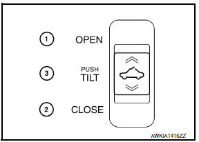
(1) OPEN
(2) CLOSE
(3) PUSH/TILT
OPERATION DESCRIPTION
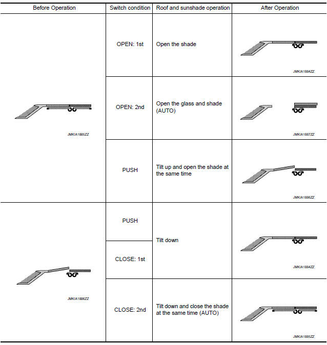
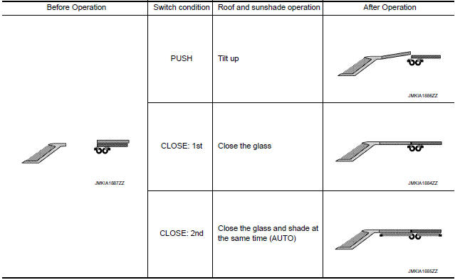
The sunroof and sunshade operate to the following condition by the sunroof switch operation.
AUTO OPERATION
The sunroof or sunshade operate automatically to the fully-open or fully-close position by operating the sunroof switch to the OPEN (2nd) or CLOSE (2nd) position.
RETAINED POWER OPERATION
Retained power operation is an additional power supply function that enables the sunroof system to operate for 45 seconds after ignition switch is turned OFF.
Retained power function cancel conditions
- Front door CLOSE (door switch OFF)→OPEN (door switch ON)
- Ignition switch is ON again.
- Timer passed (45 seconds)
ANTI-PINCH FUNCTION
CAUTION: There are some small distances immediately before the closed position which cannot be detected.
- The CPU of sunroof motor assembly monitors the sunroof
condition by the signals from sunroof motor.
When sunroof motor assembly detects an interruption during auto operation (close or tilt down operation), sunroof motor will tilt up or open [150 mm (5.91 in) or more] sunroof.
- The CPU of sunshade motor assembly monitors the sunshade condition by the signals from sunshade motor. When sunshade motor assembly detects an interruption during auto close operation, sunshade motor will open [150 mm (5.91 in) or more] sunshade.
Component Parts Location
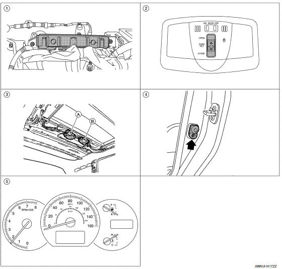
- BCM M16, M17, M18 (view with instrument panel removed)
- Sunroof switch R14
- A: Sunroof motor assembly R101 B: Sunshade motor assembly R102 (view with headlining removed)
- Front door switch LH B8, RH B108 5. Combination meter M24
Component Description

 Diagnosis system (BCM)
COMMON ITEM
CONSULT Function (BCM - COMMON ITEM)
APPLICATION ITEM
CONSULT performs the following functions via CAN communication with BCM.
SYSTEM APPLICATION
BCM can perform the following funct ...
Other materials:
B1118 - B1120 satellite sensor LH
Description
DTC B1118 - B1120 SATELLITE SENSOR LH
The satellite sensor LH is wired to the air bag diagnosis sensor unit. The
air bag diagnosis sensor unit willmonitor the satellite sensor LH for
internal failures and its circuits for communication errors.
PART LOCATION
DTC Logic
DTC DETECTI ...
Hands-free phone system
System Diagram
System Description
Refer to the Owner's Manual for Bluetooth telephone system operating
instructions. NOTE: Cellular
telephones must have their wireless connection set up (paired) before using the
Bluetooth telephone system. Bluetooth telephone system allows users
who have ...
P1801 vias control solenoid valve 2
Description
The VIAS control solenoid valve 2 cuts the intake manifold vacuum signal for
power valve 2 control. It
responds to ON/OFF signals from the ECM. When the solenoid is OFF, the vacuum
signal from the intake
manifold is cut. When the ECM sends an ON signal the coil pulls the plunger ...
Nissan Maxima Owners Manual
- Illustrated table of contents
- Safety-Seats, seat belts and supplemental restraint system
- Instruments and controls
- Pre-driving checks and adjustments
- Monitor, climate, audio, phone and voice recognition systems
- Starting and driving
- In case of emergency
- Appearance and care
- Do-it-yourself
- Maintenance and schedules
- Technical and consumer information
Nissan Maxima Service and Repair Manual

0.0093