Nissan Maxima Service and Repair Manual: Basic inspection
DIAGNOSIS AND REPAIR WORKFLOW
Work Flow
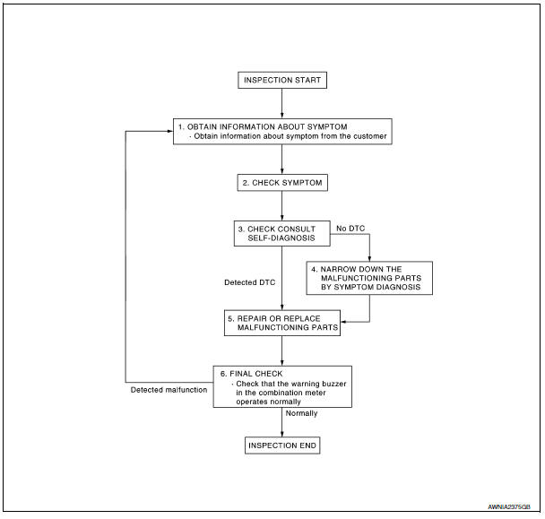
OVERALL SEQUENCE
DETAILED FLOW
1.OBTAIN INFORMATION ABOUT SYMPTOM
Interview the customer to obtain as much information as possible about the conditions and environment under which the malfunction occurred.
>> GO TO 2
2.CHECK SYMPTOM
- Check the symptom based on the information obtained from the customer.
- Check to see if any other malfunctions are present.
>> GO TO 3
3.CHECK CONSULT SELF-DIAGNOSIS RESULTS
Connect CONSULT and perform "SELF-DIAGNOSIS". Refer to MWI-29, "CONSULT Function (METER/ M&A)".
4.NARROW DOWN MALFUNCTIONING PARTS THROUGH SYMPTOM DIAGNOSIS
Perform symptom diagnosis and repair or replace the identified malfunctioning parts.
>> GO TO 5
5.REPAIR OR REPLACE MALFUNCTIONING PARTS
Repair or replace malfunctioning parts.
NOTE:
If DTC is displayed, erase DTC after repairing or replacing malfunctioning parts.
>> GO TO 6
6.FINAL CHECK
Check that the warning buzzer in the combination meter operates normally.


Other materials:
Electric ignition system
System Diagram
System Description
INPUT/OUTPUT SIGNAL CHART
*1: This signal is sent to the ECM via the CAN communication line.
*2: ECM determines the start signal status by the signals of engine speed and
battery voltage.
SYSTEM DESCRIPTION
Ignition order: 1 - 2 - 3 - 4 - 5 - 6
The ...
Main line between HVAC and A-bag circuit
Diagnosis Procedure
1.CHECK HARNESS CONTINUITY (OPEN CIRCUIT)
Turn the ignition switch OFF.
Disconnect the battery cable from the negative terminal.
Disconnect the following harness connectors.
A/C auto amp.
Harness connectors M1 and E30
Check the continuity between the A/C au ...
Front seat
Exploded View
DRIVER
Driver Seat - Without Climate Controlled Seats
Headrest
Headrest holder (free)
Headrest holder (locked)
Seatback board
Seatback board clip
Seat cushion inner finisher inside (RH)
Recline mechanism inner cover
Seat cushion outer finisher (RH)
Seat be ...
Nissan Maxima Owners Manual
- Illustrated table of contents
- Safety-Seats, seat belts and supplemental restraint system
- Instruments and controls
- Pre-driving checks and adjustments
- Monitor, climate, audio, phone and voice recognition systems
- Starting and driving
- In case of emergency
- Appearance and care
- Do-it-yourself
- Maintenance and schedules
- Technical and consumer information
Nissan Maxima Service and Repair Manual

0.0052