Nissan Maxima Service and Repair Manual: Front fog lamp circuit
Description
The IPDM E/R (intelligent power distribution module engine room) controls the front fog lamp relay based on inputs from the BCM over the CAN communication lines. When the front fog lamp relay is energized, power flows from the front fog lamp relay in the IPDM E/R to the front fog lamps.
Component Function Check
1.CHECK FRONT FOG LAMP OPERATION
WITHOUT CONSULT
- Activate IPDM E/R auto active test. Refer to PCS-11, "Diagnosis Description".
- Check that the front fog lamp is turned ON.
CONSULT
- Select "EXTERNAL LAMPS" of IPDM E/R active test item.
- While operating the test item, check that the front fog lamp is turned ON.
FOG : Front fog lamp ON
OFF : Front fog lamp OFF
Diagnosis Procedure
1.CHECK FRONT FOG LAMP FUSE
- Turn the ignition switch OFF.
- Check that the following fuse is not open.

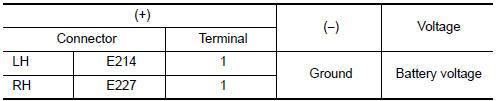
2.CHECK FRONT FOG LAMP OUTPUT VOLTAGE
CONSULT
- Turn the ignition switch OFF.
- Disconnect the front fog lamp connector.
- Turn the ignition switch ON.
- Select "EXTERNAL LAMPS" of IPDM E/R active test item.
- With EXTERNAL LAMPS ON, check the voltage between the fog lamp connector and ground.
3.CHECK FRONT FOG LAMP OPEN CIRCUIT
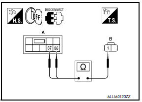
- Turn the ignition switch OFF.
- Disconnect IPDM E/R connector E200.
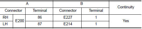
- Check continuity between the IPDM E/R harness connector (A) and the front fog lamp harness connector (B).
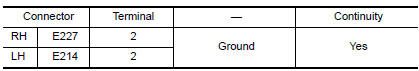
4.CHECK FRONT FOG LAMP GROUND CIRCUIT
Check continuity between the front fog lamp harness connector terminal and ground.
 Headlamp (LO) circuit
Description
The IPDM E/R (intelligent power distribution module engine room) controls the
headlamp low relay based on inputs from the BCM over the CAN communication
lines. When the headlamp low r ...
 Parking lamp circuit
Description
The IPDM E/R (intelligent power distribution module engine room) controls the
tail lamp relay based on inputs from the BCM over the CAN communication
lines. When the tail lamp relay i ...
Other materials:
Exterior lighting system symptoms
Symptom Table
CAUTION: Perform the self-diagnosis with CONSULT
before the symptom diagnosis. Perform the trouble diagnosis if any DTC is
detected.
NORMAL OPERATING CONDITION
Description
AUTO LIGHT SYSTEM
The auto light system may not turn the headlamp ON/OFF immediately after
passing ...
System temporarily unavailable
When radar blockage is detected, the system will
be deactivated automatically. The "Side Radar
Obstruction" warning message will appear and
the BSW/RCTA indicator (white) will blink A in
the vehicle information display.
The systems are not available until the conditions
no longer exist.
...
Headlamp
System Diagram
System Description
Control of the headlamp system is dependent upon the position of the
combination switch (lighting and turn signal switch). When the lighting
switch is placed in the 2nd position, the BCM (body control module) receives
input requesting the headlamps and par ...
Nissan Maxima Owners Manual
- Illustrated table of contents
- Safety-Seats, seat belts and supplemental restraint system
- Instruments and controls
- Pre-driving checks and adjustments
- Monitor, climate, audio, phone and voice recognition systems
- Starting and driving
- In case of emergency
- Appearance and care
- Do-it-yourself
- Maintenance and schedules
- Technical and consumer information
Nissan Maxima Service and Repair Manual

0.0137