Nissan Maxima Service and Repair Manual: Headlamp (LO) circuit
Description
The IPDM E/R (intelligent power distribution module engine room) controls the headlamp low relay based on inputs from the BCM over the CAN communication lines. When the headlamp low relay is energized, power flows through fuses 51 and 52, located in the IPDM E/R. Power then flows to the front combination lamps to the headlamp low beam.
Component Function Check
1.CHECK HEADLAMP (LO) OPERATION
WITHOUT CONSULT
- Start IPDM E/R auto active test. Refer to PCS-11, "Diagnosis Description".
- Check that the headlamp is turned ON.
NOTE: HI/LO is repeated 1 second each when using the IPDM E/R auto active test.
CONSULT
- Select "EXTERNAL LAMPS" of IPDM E/R active test item.
- While operating the test item, check that the headlamp is turned ON.
LO : Headlamp ON
OFF : Headlamp OFF
Diagnosis Procedure
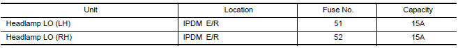
1.CHECK HEADLAMP (LO) FUSES
- Turn the ignition switch OFF.
- Check that the following fuses are not open.
2.CHECK HEADLAMP (LO) OUTPUT VOLTAGE
CONSULT
- Turn the ignition switch OFF.
- Disconnect the front combination lamp connector.
- Turn the ignition switch ON.
- Select "EXTERNAL LAMPS" of IPDM E/R active test item.
- With EXTERNAL LAMPS ON, check the voltage between the combination lamp connector and ground.
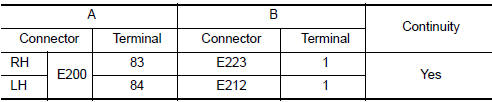
3.CHECK HEADLAMP (LO) CIRCUIT FOR OPEN
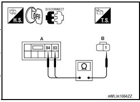
- Turn the ignition switch OFF.
- Disconnect IPDM E/R connector E200.
- Check continuity between the IPDM E/R harness connector (A) and the front combination lamp harness connector (B
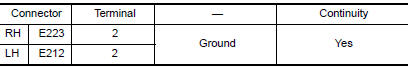
4.CHECK FRONT COMBINATION LAMP (LO) GROUND CIRCUIT
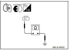
- Disconnect the front combination lamp connector.
- Check continuity between the front combination lamp harness connector terminal and ground.
 Headlamp (HI) circuit
Description
The IPDM E/R (intelligent power distribution module engine room) controls the
headlamp high relay based on inputs from the BCM over the CAN communication
lines. When the headlamp high ...
 Front fog lamp circuit
Description
The IPDM E/R (intelligent power distribution module engine room) controls the
front fog lamp relay based on inputs from the BCM over the CAN communication
lines. When the front fog la ...
Other materials:
B2110 transmission range switch
Description
IPDM E/R confirms the shift position with the following
signals.
Transmission range switch
Shift position signal from BCM (CAN)
DTC Logic
DTC DETECTION LOGIC
NOTE:
If DTC B2110 is displayed with DTC
U1000, first perform the trouble diagnosi ...
Refrigerant pressure sensor
Description
The refrigerant pressure sensor is installed at the condenser of the air
conditioner system. The sensor uses an
electrostatic volume pressure transducer to convert refrigerant pressure to
voltage. The voltage signal is sent
to ECM, and ECM controls cooling fan system.
Compo ...
Ducts and grilles
Exploded View
Ducts
Side defroster nozzle (RH)
Front defroster nozzle
Side defroster nozzle (LH)
Upper ventilator duct
Heater and cooling unit assembly
Connector duct (LH)
Floor ventilator duct (LH)
Rear floor duct (LH)
Connector duct (center)
Rear ventilator duct (cen ...
Nissan Maxima Owners Manual
- Illustrated table of contents
- Safety-Seats, seat belts and supplemental restraint system
- Instruments and controls
- Pre-driving checks and adjustments
- Monitor, climate, audio, phone and voice recognition systems
- Starting and driving
- In case of emergency
- Appearance and care
- Do-it-yourself
- Maintenance and schedules
- Technical and consumer information
Nissan Maxima Service and Repair Manual

0.01