Nissan Maxima Service and Repair Manual: Headlamp (HI) circuit
Description
The IPDM E/R (intelligent power distribution module engine room) controls the headlamp high relay based on inputs from the BCM over the CAN communication lines. When the headlamp high relay is energized, power flows through fuses 48 and 49, located in the IPDM E/R. Power then flows to the front combination lamps to the headlamp high beam.
Component Function Check
1.CHECK HEADLAMP (HI) OPERATION
WITHOUT CONSULT
- Start IPDM E/R auto active test. Refer to PCS-11, "Diagnosis Description".
- Check that the headlamp switches to the high beam.
NOTE: HI/LO is repeated 1 second each when using the IPDM E/R auto active test.
CONSULT
- Select "EXTERNAL LAMPS" of IPDM E/R active test item.
- While operating the test item, check that the headlamp switches to the high beam.
HI : Headlamp switches to the high beam.
OFF : Headlamp OFF
Diagnosis Procedure
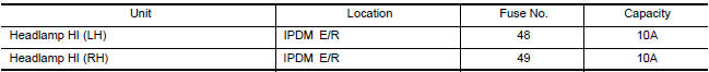
1.CHECK HEADLAMP (HI) FUSES
- Turn the ignition switch OFF.
- Check that the following fuses are not open.
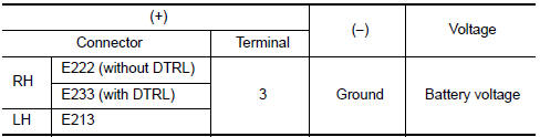
2.CHECK HEADLAMP (HI) OUTPUT VOLTAGE
CONSULT ACTIVE TEST
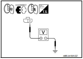
- Turn the ignition switch OFF.
- Disconnect the front combination lamp connector.
- Turn the ignition switch ON.
- Select "EXTERNAL LAMPS" of IPDM E/R active test item.
- With EXTERNAL LAMP ON, check the voltage between the combination lamp connector and ground.
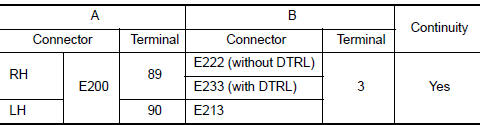
3.CHECK HEADLAMP (HI) CIRCUIT FOR OPEN
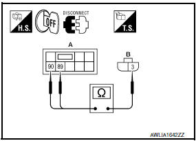
- Turn the ignition switch OFF.
- Disconnect IPDM E/R connector E200.
- Check continuity between the IPDM E/R harness connector (A) and the front combination lamp harness connector (B).
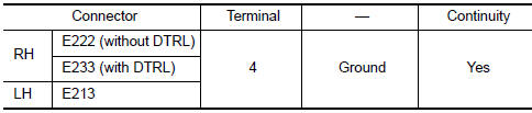
4.CHECK FRONT COMBINATION LAMP (HI) GROUND CIRCUIT
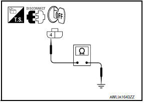
Check continuity between the front combination lamp harness connector terminal and ground.
5.CHECK CONTINUITY BETWEEN FRONT COMBINATION LAMP RH (HI) AND DAYTIME LIGHT RELAY

- Disconnect daytime light relay connector.
- Check continuity between front combination lamp RH harness connector and daytime light relay harness connector.
6.CHECK DAYTIME LIGHT RELAY GROUND CIRCUIT
Check continuity between daytime light relay harness connector and ground.

7.CHECK DAYTIME LIGHT RELAY FUSE
- Turn the ignition switch OFF.
- Check that the following fuse is not open.

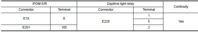
8.CHECK DAYTIME LIGHT RELAY CIRCUIT FOR OPEN
- Disconnect IPDM E/R connector E18 and E201.
- Check continuity between the IPDM E/R harness connector and the daytime light relay harness connector.
9.CHECK DAYTIME LIGHT RELAY
Check daytime light relay
Component Inspection
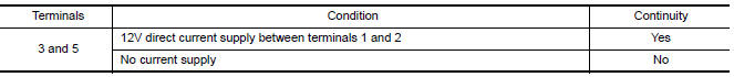
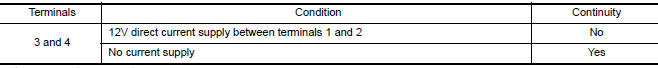
1. CHECK DAYTIME LIGHT RELAY
- Turn ignition switch OFF.
- Remove daytime light relay.
- Check the continuity between daytime light relay terminals under the following conditions.
 Power supply and ground circuit
BCM (BODY CONTROL MODULE)
BCM (BODY CONTROL MODULE) : Diagnosis Procedure
1. CHECK FUSE AND FUSIBLE LINK
Check if the following BCM fuses or fusible link are blown.
2. CHECK POWER SUPPLY CIRCU ...
 Headlamp (LO) circuit
Description
The IPDM E/R (intelligent power distribution module engine room) controls the
headlamp low relay based on inputs from the BCM over the CAN communication
lines. When the headlamp low r ...
Other materials:
Precaution
PRECAUTIONS
Precaution for Supplemental Restraint System (SRS) "AIR BAG" and
"SEAT BELT PRE-TENSIONER"
The Supplemental Restraint System such as "AIR BAG" and "SEAT BELT
PRE-TENSIONER", used along with a front seat belt, helps to reduce the risk
or severity of injury to the driver and front ...
AV control unit
Reference Value
VALUES ON THE DIAGNOSIS TOOL
CONSULT data monitor item
TERMINAL LAYOUT
PHYSICAL VALUES
DTC Index
SELF-DIAGNOSIS RESULTS DISPLAY ITEM
...
B2618 BCM
Description
BCM controls the various electrical components and simultaneously supplies
power according to the power
supply position.
BCM checks the power supply position internally.
DTC Logic
DTC DETECTION LOGIC
NOTE:
If DTC B2618 is displayed with DTC U1000, first perform the
trou ...
Nissan Maxima Owners Manual
- Illustrated table of contents
- Safety-Seats, seat belts and supplemental restraint system
- Instruments and controls
- Pre-driving checks and adjustments
- Monitor, climate, audio, phone and voice recognition systems
- Starting and driving
- In case of emergency
- Appearance and care
- Do-it-yourself
- Maintenance and schedules
- Technical and consumer information
Nissan Maxima Service and Repair Manual

0.0068