Nissan Maxima Service and Repair Manual: Power supply and ground circuit
BCM (BODY CONTROL MODULE)
BCM (BODY CONTROL MODULE) : Diagnosis Procedure
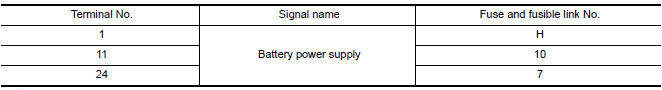
1. CHECK FUSE AND FUSIBLE LINK
Check if the following BCM fuses or fusible link are blown.
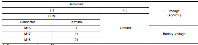
2. CHECK POWER SUPPLY CIRCUIT
- Turn ignition switch OFF.
- Disconnect BCM.
- Check voltage between BCM harness connector and ground.
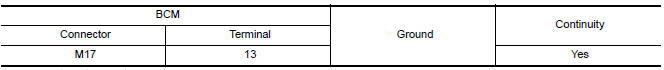
3. CHECK GROUND CIRCUIT
Check continuity between BCM harness connector and ground
BCM (BODY CONTROL MODULE) : Special Repair Requirement
1. REQUIRED WORK WHEN REPLACING BCM
IPDM E/R (INTELLIGENT POWER DISTRIBUTION MODULE ENGINE ROOM)
IPDM E/R (INTELLIGENT POWER DISTRIBUTION MODULE ENGINE ROOM) : Diagnosis Procedure
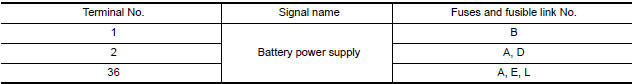
1. CHECK FUSES AND FUSIBLE LINK
Check that the following IPDM E/R fuses or fusible link are not blown.
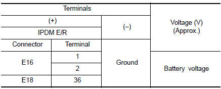
2. CHECK POWER SUPPLY CIRCUIT
- Turn ignition switch OFF.
- Disconnect IPDM E/R connectors.
- Check voltage between IPDM E/R harness connector and ground.
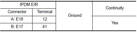
3. CHECK GROUND CIRCUIT
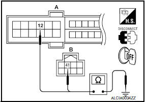
Check continuity between IPDM E/R harness connectors and ground.

 Headlamp (HI) circuit
Description
The IPDM E/R (intelligent power distribution module engine room) controls the
headlamp high relay based on inputs from the BCM over the CAN communication
lines. When the headlamp high ...
Other materials:
Exterior and interior lights
Always check with the Parts Department at a NISSAN dealer for the latest
parts information.
* It is recommended that you visit a NISSAN dealer for replacement.
1. Map light
2. Personal light
3. Step light
4. Door mirror turn signal light (if so
equipped)
5. Headlight assembly
6. ...
AV control unit
Removal and Installation
AV control unit
AV control unit bracket LH
AV control unit bracket RH
A/C auto amp.
Cluster lid C (with A/C and AV switch assembly attached)
Clip
AV CONTROL UNIT
Removal
CAUTION: Before replacing AV control unit,
perform "READ CONFIGURATION" to s ...
Lifting switch (rear)
Description
Lifting switch (rear) is equipped to the power seat switch LH on the seat
frame. The operation signal is inputted to the driver seat control unit when
the lifting switch (rear) is operated.
Component Function Check
1. CHECK FUNCTION
Select "LIFT RR SW-UP", "LIFT RR SW-DN" in " ...
Nissan Maxima Owners Manual
- Illustrated table of contents
- Safety-Seats, seat belts and supplemental restraint system
- Instruments and controls
- Pre-driving checks and adjustments
- Monitor, climate, audio, phone and voice recognition systems
- Starting and driving
- In case of emergency
- Appearance and care
- Do-it-yourself
- Maintenance and schedules
- Technical and consumer information
Nissan Maxima Service and Repair Manual

0.0056