Nissan Maxima Service and Repair Manual: Heater & cooling unit assembly
Exploded View
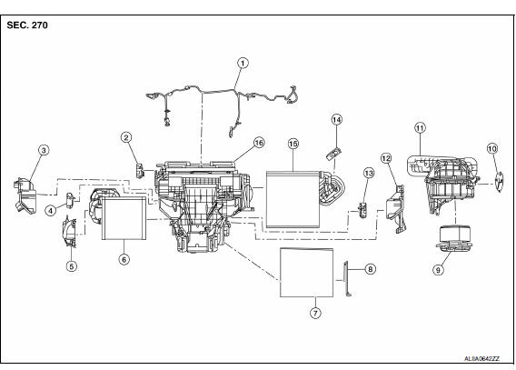
- Wiring harness
- Mode door motor
- Upper floor connecting duct (LH)
- Air mix door motor (driver side)
- Heater core pipes cover
- Heater core
- In-cabin microfilter
- Filter cover
- Blower motor
- Intake door motor
- Blower unit
- Upper floor connecting duct (RH)
- Air mix door motor (passenger side)
- Expansion valve
- Evaporator
- Heating and cooling unit assembly
NOTE: When removing components such as hoses, tubes/lines, etc., cap or plug openings to prevent fluid from spilling.
HEATER & COOLING UNIT ASSEMBLY
HEATER & COOLING UNIT ASSEMBLY : Removal and Installation
REMOVAL
CAUTION: Before servicing, turn the ignition switch off, disconnect both battery terminals and wait at least three minutes.
- Discharge the refrigerant. Refer to HA-28, "Recycle Refrigerant".
- Drain the engine coolant. Refer to CO-11, "Changing Engine Coolant".
- Disconnect the battery negative and positive terminals.
- Remove the front wiper drive assembly. Refer to WW-78, "FRONT WIPER ARMS : Removal and Installation".
- Remove the strut tower bar. Refer to FSU-13, "Exploded View".
- Disconnect the heater hoses from the heater core pipes.
- Disconnect the high-pressure pipe and low-pressure pipe from the expansion valve. Refer to HA-42, "Exploded View". CAUTION: Cap or wrap the pipe joint with a suitable material such as vinyl tape to avoid the entry of air.
- Remove the instrument panel assembly. Refer to IP-11, "Removal and Installation".
- Remove the steering column assembly. Refer to ST-23, "Removal and Installation".
- Disconnect the drain hose.
- Remove the interior fuse block (J/B). Refer to PG-62, "Terminal Arrangement".
- Remove the LH, RH and center connector ducts. Refer to VTL-11, "REAR FLOOR DUCTS : Removal and Installation".
- Remove the steering member center stay.
- Remove the heating and cooling unit assembly attached to the steering member as one assembly from the vehicle.
- Remove the blower unit from the heating and cooling unit and steering member assembly.
- Remove the heating and cooling unit from the steering member.
INSTALLATION
Installation is in the reverse order of removal.
HEATER CORE
HEATER CORE : Removal and Installation
REMOVAL
- Remove the heating and cooling unit assembly. Refer to HA-47, "HEATER & COOLING UNIT ASSEMBLY : Removal and Installation".
- Remove the heater core pipes cover. Refer to HA-47, "Exploded View".
- Remove the heater core.
INSTALLATION
Installation is in the reverse order of removal.
CAUTION: Make sure that the aspirator hose is securely attached to the aspirator on the upper floor connecting duct LH.
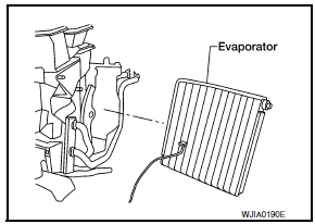
EVAPORATOR
EVAPORATOR : Removal and Installation
REMOVAL
- Remove the heating and cooling unit assembly. Refer to HA-28, "Recycle Refrigerant".
- Remove the upper floor connecting duct RH. Refer to HA-47, "Exploded View".
- Remove the evaporator.
- Remove the expansion valve from the evaporator.
- Remove the intake sensor.
CAUTION:
- Mark the mounting position of the intake sensor.
INSTALLATION
Installation is in the reverse order of removal.
CAUTION:
- Do not reuse O-rings.
- Apply A/C oil to the new O-rings for installation.
- After charging refrigerant, check for leaks.
EXPANSION VALVE
EXPANSION VALVE : Removal and Installation for Expansion Valve
REMOVAL
- Discharge the refrigerant. Refer to HA-28, "Recycle Refrigerant".
- Remove the hoodledge covers (LH/RH).
- Remove the strut tower bar. Refer to FSU-13, "Exploded View".
- Remove the cowl top grille. Refer to EXT-21, "Removal and Installation".
- Remove the lower cowl top extension RH.
- Disconnect the high-pressure pipe and low-pressure pipe from the expansion valve. CAUTION: Cap or wrap the joint of the pipe with suitable material such as vinyl tape to avoid the entry of air.
- Remove the expansion valve.
INSTALLATION
Installation is in the reverse order of removal.
CAUTION:
- Do not reuse O-rings.
- Apply A/C oil to the new O-rings for installation.
- After charging refrigerant, check for leaks
 Condenser
CONDENSER
CONDENSER : Removal and Installation
REMOVAL
Discharge the refrigerant. Refer to HA-28, "Recycle Refrigerant".
Remove the RH hoodledge cover.
Remove the front bumper fascia. Refer ...
 Service data and specifications (SDS)
SERVICE DATA AND SPECIFICATIONS (SDS)
Compressor
Oil
Refrigerant
...
Other materials:
If your vehicle is stolen
If your vehicle is stolen, you should change the
codes of any non-rolling code device that has
been programmed into HomeLink. Consult the
Owner's Manual of each device or call the manufacturer
or dealer of those devices for additional
information.
When your vehicle is recovered, you will
need ...
Combination meter
Reference Value
VALUES ON THE DIAGNOSIS TOOL
NOTE:
* The monitor will indicate "OFF" even though
the brake warning lamp is on if either of the following conditions exist:
The parking brake is engaged
The brake fluid level is low
TERMINAL LAYOUT
PHYSICAL VALUES
...
Diagnosis system (bluetooth control unit)
Diagnosis Description
The Bluetooth control unit has two diagnostic checks. The first diagnostic
check is performed automatically every ignition cycle during control unit
initialization. The second diagnostic check is performed by the technician
using the steering wheel audio control switches ...
Nissan Maxima Owners Manual
- Illustrated table of contents
- Safety-Seats, seat belts and supplemental restraint system
- Instruments and controls
- Pre-driving checks and adjustments
- Monitor, climate, audio, phone and voice recognition systems
- Starting and driving
- In case of emergency
- Appearance and care
- Do-it-yourself
- Maintenance and schedules
- Technical and consumer information
Nissan Maxima Service and Repair Manual

0.0054