Nissan Maxima Service and Repair Manual: Removal and installation
COMPRESSOR
Removal and Installation for Compressor
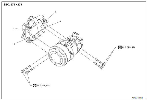
REMOVAL
CAUTION: Before servicing, turn the ignition switch off, disconnect both battery terminals and wait at least three minutes.
- Disconnect the battery negative and positive terminals. Refer to PG-67, "Removal and Installation (Battery)"
- Discharge the refrigerant. Refer to HA-28, "Recycle Refrigerant".
- Partially drain the engine cooling system. Refer to CO-11, "Changing Engine Coolant".
- Remove the front RH wheel and tire using a power tool. Refer to WT-60, "Adjustment".
- Remove the engine under cover. Refer to EXT-15, "Exploded View".
- Remove the RH fender protector side cover and the RH fender protector. Refer to EXT-24, "Removal and Installation".
- Remove the engine room cover.
- Remove the air cleaner assembly. Refer to EM-24, "Removal and Installation".
- Remove the upper radiator hose.
- Remove the battery and battery tray. Refer to PG-68, "Removal and Installation (Battery Tray)".
- Remove the engine cooling fan and shroud assembly. Refer to CO-16, "Removal and Installation".
- Disconnect the high-pressure flexible hose and low-pressure flexible hose from the compressor. CAUTION: Cap or wrap the joint of the hose with suitable material such as vinyl tape to avoid the entry of air.
- Reposition the power steering hose out of the way.
- Disconnect the harness connector from the compressor.
- Release the drive belt tension and reposition the drive belt off of the compressor clutch pulley. Refer to EM-14, "Removal and Installation".
- Remove the RH compressor bolts.
- Remove the front compressor bolts using a power tool.
- Disconnect the compressor wire harness clip from the compressor.
- Remove the compressor.
INSTALLATION
Installation is in the reverse order of removal.
CAUTION:
- For installation, tighten the compressor bolts in the order as shown.
- Do not reuse O-rings.
- Apply A/C oil to the O-rings of the low-pressure flexible hose and high-pressure flexible hose for installation.
- After charging the A/C refrigerant, check for leaks. Refer to HA-33, "Inspection".
Removal and Installation for Compressor Clutch
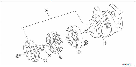
- Magnetic clutch assembly
- Clutch disk
- Snap ring
- Pulley
- Magnet coil
- Compressor
NOTE: Illustrations shown with the compressor out of the vehicle are for clarity, it is not necessary to remove the compressor.
REMOVAL
- Remove the front wheel and tire (RH). Refer to WT-60, "Adjustment".
- Remove the engine under cover. Refer to EXT-15, "Exploded View".
- Release the drive belt from the A/C pulley. Refer to EM-14, "Removal and Installation".
- Reposition the power steering line aside, do not disconnect the power steering line.
- Remove the center bolt by holding the clutch disc steady using a suitable tool.
- Remove the clutch disc and shims.
CAUTION: Retain all the shims for installation.
- Remove the snap ring using a suitable tool as shown
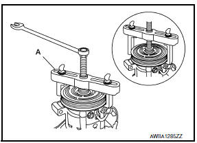
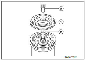
- Remove the pulley assembly using a suitable tool (A) as shown.
CAUTION:
- To prevent deformation of the pulley groove, the puller claws should be hooked under (not into) the pulley groove.
- Disconnect the magnet coil harness.
- Remove the three magnet coil screws using a suitable tool as shown, then remove the magnet coil.
INSPECTION AFTER REMOVAL
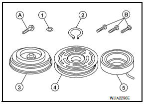
- Shim (1)
- Snap ring (2)
- Clutch disc (3)
- Pulley (4)
- Magnet coil (5)
- Center bolt (A)
- Magnet coil screws (B)
Clutch Disc
If the contact surface shows signs of damage due to excessive heat, replace the clutch disc and pulley.
Pulley
Check the appearance of the pulley assembly. If the contact surface of the pulley shows signs of excessive grooving, replace the clutch disc and pulley. The contact surfaces of the pulley assembly should be cleaned with a suitable solvent before installation.
Magnet Coil
Check the magnet coil for a loose connection or cracked insulation. Replace as necessary.
INSTALLATION
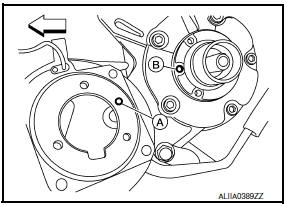
- Install the magnet coil by aligning the magnet coil pin (A) with the hole (B) in the compressor front head as shown, then install the magnet coil screws.
 : Front
CAUTION:
- Be sure to align the magnet coil pin with the hole in the compressor front head.
- Connect the magnet coil harness.
- Install the pulley assembly using Tool and a wrench as shown, then install the snap ring using a suitable tool.
Tool number : - (J-38873-A)
- Install the clutch disc (1) on the drive shaft, together with all of the original shim(s) (2) using a suitable tool (A).
- Install the center bolt using suitable tool.
Center bolt : 12 N*m (1.2 kg-m, 9 ft-lb)
- After tightening the center bolt to specification, check that the pulley rotates smoothly.
- Reposition the power steering line back into position, do not disconnect the power steering line.
- Install the drive belt back onto the A/C pulley. Refer to EM-14, "Removal and Installation".
- Install the engine under cover. Refer to EXT-15, "Exploded View".
- Install the front wheel and tire (RH). Refer to WT-60, "Adjustment".
INSPECTION AFTER INSTALLATION
Check the clearance (B) all the way around between the clutch disc (1) and pulley (2) using a suitable tool (A) as shown.
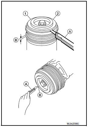
Clutch disc-to-pulley clearance (B) : 0.3 - 0.6 mm (0.012 - 0.024 in)
If the specified clearance (B) is not obtained, replace the adjusting shim(s) and recheck the clearance (B) as shown.
BREAK-IN OPERATION
When replacing compressor clutch assembly, always conduct the break-in operation. This is done by engaging and disengaging the clutch about 30 times. Break-in operation raises the level of transmitted torque.
 Performance test
Inspection
INSPECTION PROCEDURE
Connect recovery/recycling/recharging equipment (for HFC-134a) or
manifold gauge.
Start the engine, and set to the following condition.
Maintain tes ...
 Cooler pipe and hose
Exploded View
Heater and cooling unit assembly
High-pressure pipe
High-pressure A/C service valve
High-pressure flexible hose
Air deflector (RH)
Junction pipe
Condenser
Liquid ...
Other materials:
Washer level switch
Removal and Installation
REMOVAL
Position the RH front fender protector back. Refer to EXT-24,
"Removal and Installation".
Remove the engine under cover.
Remove the RH front fender protector side cover. Refer to EXT-24,
"Removal and Installation".
Disconnect the front washer level ...
P1217 engine over temperature
DTC Logic
DTC DETECTION LOGIC
NOTE:
If DTC P1217 is displayed with DTC UXXXX, first perform the
trouble diagnosis for DTC UXXXX.
Refer to EC-161, "DTC Logic".
If DTC P1217 is displayed with DTC P0607, first perform the
trouble diagnosis for DTC P0607. Refer
t ...
Rear regulator
Rear Door Glass Regulator
REMOVAL
Remove the rear door finisher. Refer to INT-21, "Removal and
Installation".
Position aside the vapor barrier.
Temporarily reconnect the power window switch and raise/lower
the door window until the glass bolts can be seen.
Remove the glass bolt ...
Nissan Maxima Owners Manual
- Illustrated table of contents
- Safety-Seats, seat belts and supplemental restraint system
- Instruments and controls
- Pre-driving checks and adjustments
- Monitor, climate, audio, phone and voice recognition systems
- Starting and driving
- In case of emergency
- Appearance and care
- Do-it-yourself
- Maintenance and schedules
- Technical and consumer information
Nissan Maxima Service and Repair Manual

0.0055