Nissan Maxima Service and Repair Manual: Automatic drive positioner control unit
Reference Value
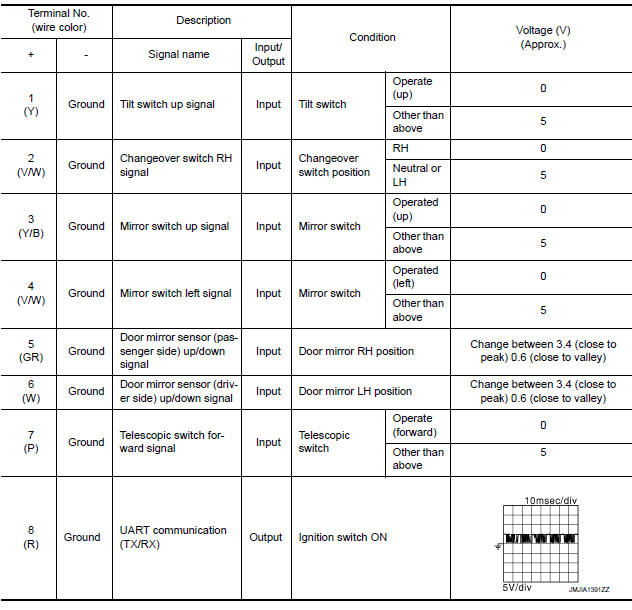
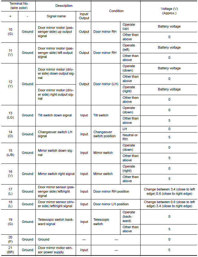
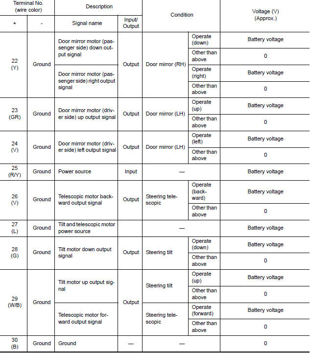
TERMINAL LAYOUT
PHYSICAL VALUES
 Driver seat control unit
Reference Value
VALUES ON THE DIAGNOSIS TOOL
CONSULT MONITOR ITEM
*: The value at the position attained when the battery is connected is
regarded as 32768.
TERMINAL LAYOUT
PHYSICAL VALU ...
 BCM (body control module)
Reference Value
NOTE: The Signal Tech II Tool (J-50190) can be used
to perform the following functions. Refer to the Signal Tech II User Guide
for additional information.
Activate and display ...
Other materials:
Trunk open function symptoms
TRUNK LID OPENER SWITCH
TRUNK LID OPENER SWITCH : Symptom Table
TRUNK OPEN FUNCTION MALFUNCTION
NOTE:
Before performing the diagnosis in the following table, check
"WORK FLOW". Refer to DLK-9, "Work Flow".
Check that vehicle is under the condition shown in "Conditions
of ve ...
Power supply and ground circuit
BCM
BCM : Diagnosis Procedure
1. CHECK FUSE AND FUSIBLE LINK
Check if the following BCM fuses or fusible link are blown.
2. CHECK POWER SUPPLY CIRCUIT
Turn ignition switch OFF.
Disconnect BCM.
Check voltage between BCM harness connector and ground.
3. CHECK GROUND CIRCUIT
Che ...
Precaution
PRECAUTIONS
Precaution for Supplemental Restraint System (SRS) "AIR BAG" and
"SEAT BELT PRE-TENSIONER"
The Supplemental Restraint System such as "AIR BAG" and "SEAT BELT
PRE-TENSIONER", used along with a front seat belt, helps to reduce the risk
or severity of injury to the driver and front ...
Nissan Maxima Owners Manual
- Illustrated table of contents
- Safety-Seats, seat belts and supplemental restraint system
- Instruments and controls
- Pre-driving checks and adjustments
- Monitor, climate, audio, phone and voice recognition systems
- Starting and driving
- In case of emergency
- Appearance and care
- Do-it-yourself
- Maintenance and schedules
- Technical and consumer information
Nissan Maxima Service and Repair Manual

0.0064