Nissan Maxima Service and Repair Manual: BCM (body control module)
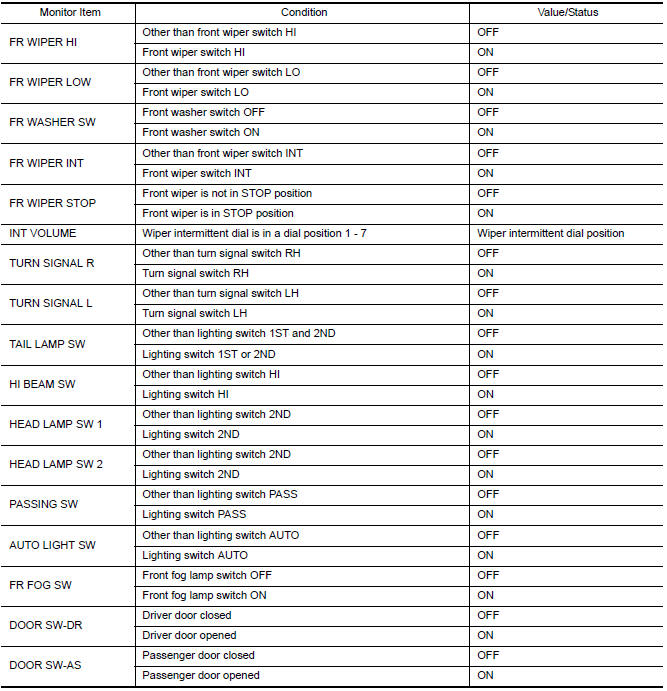
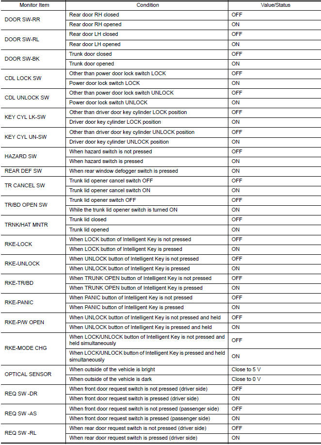
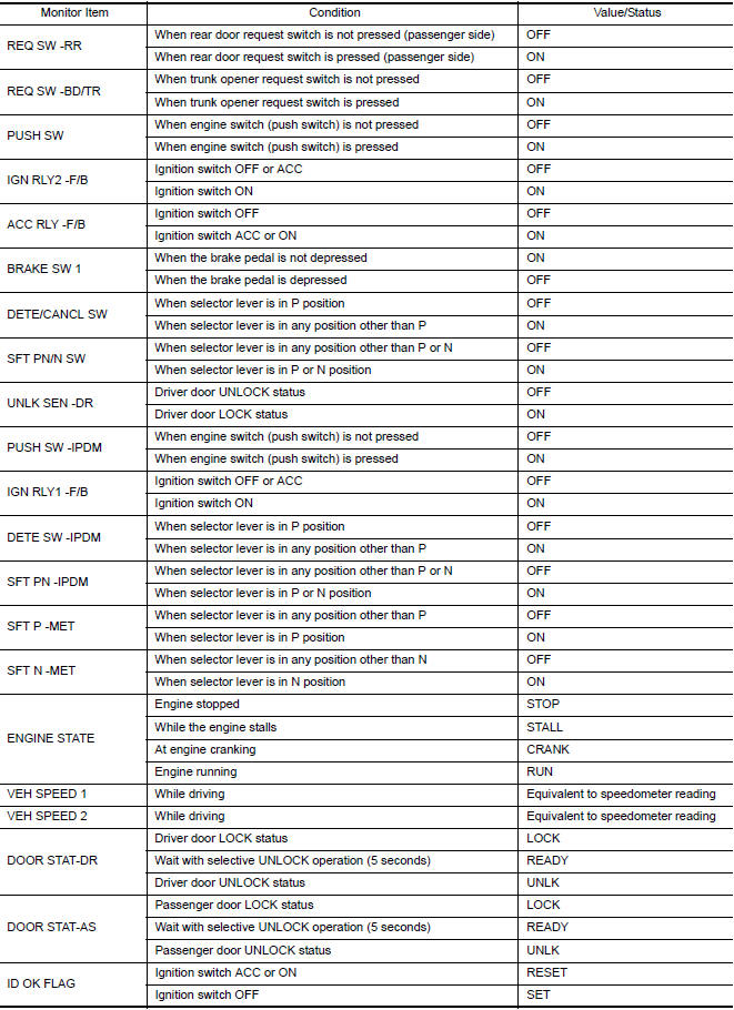
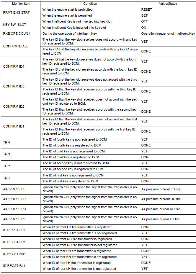
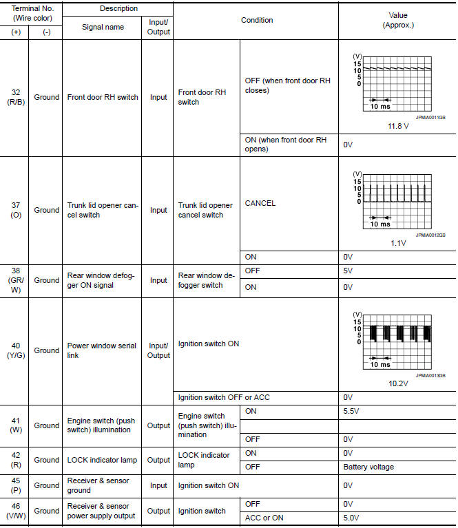
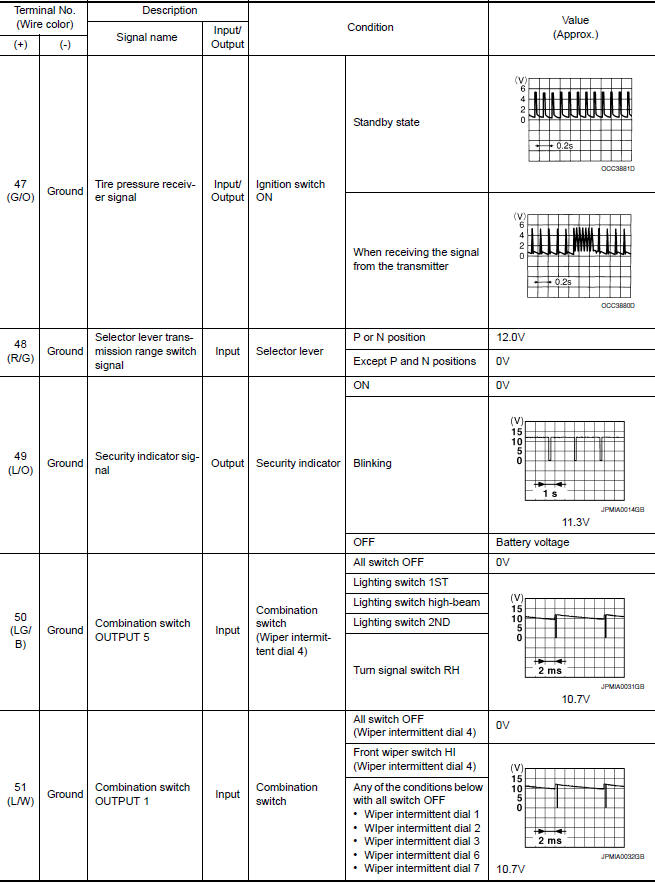
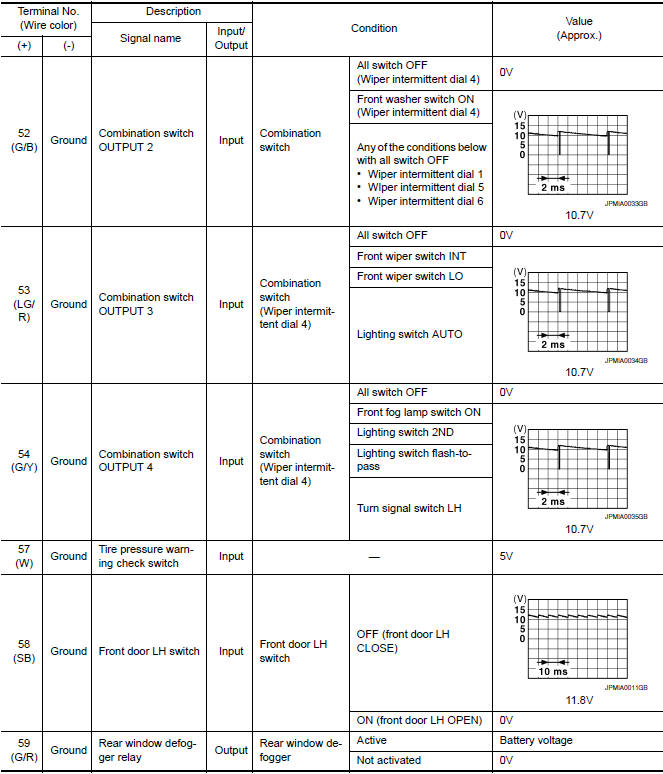
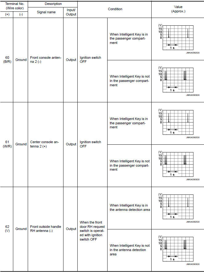
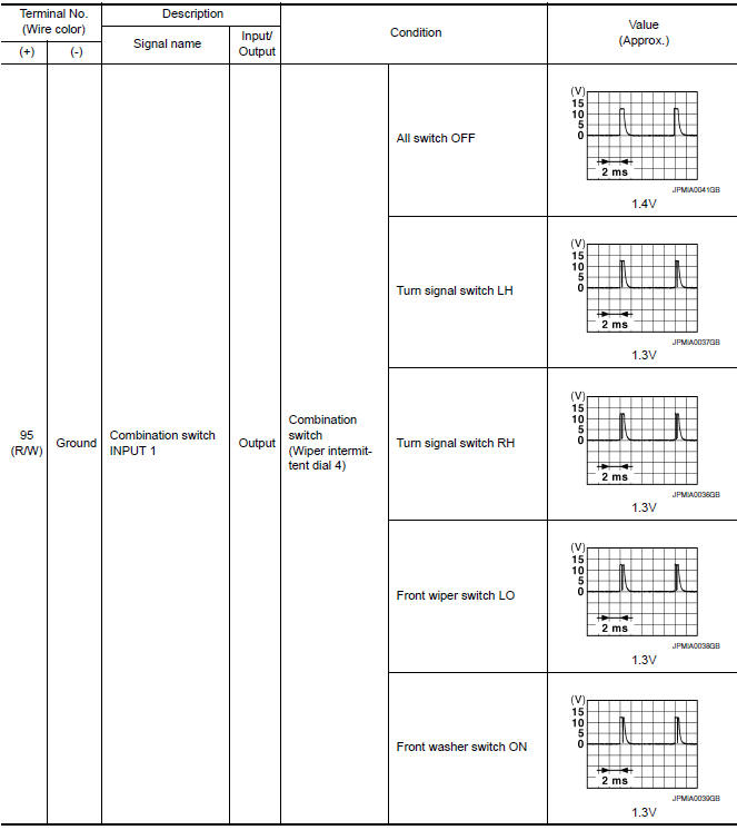
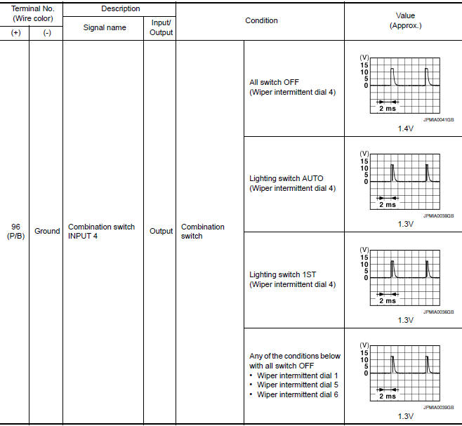
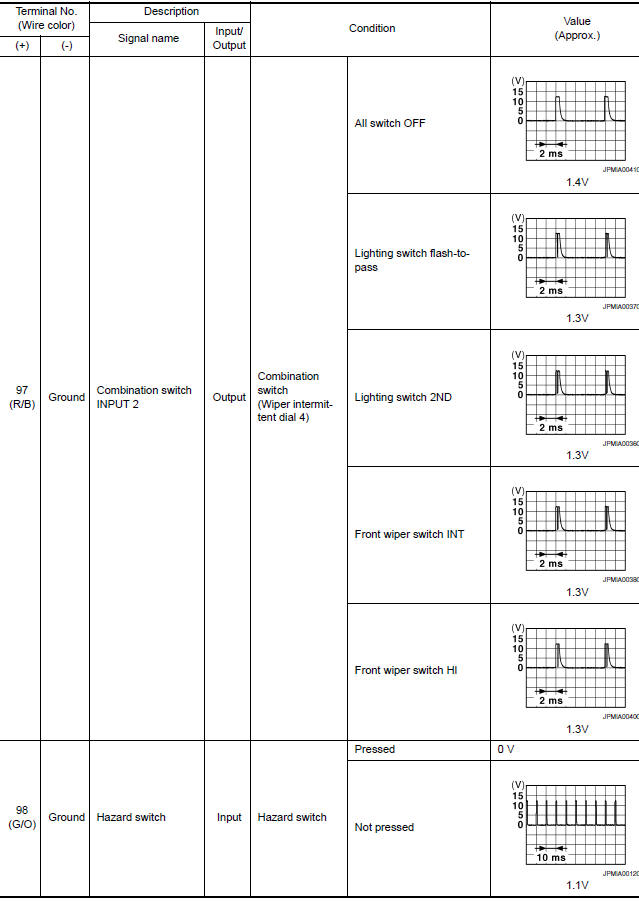
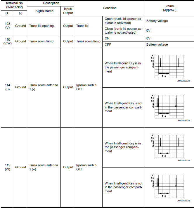
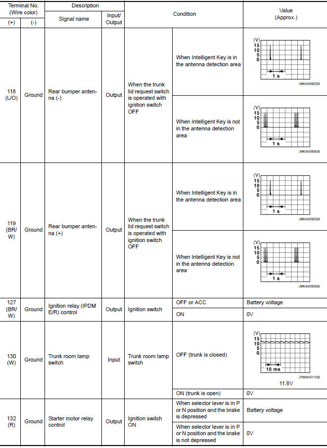
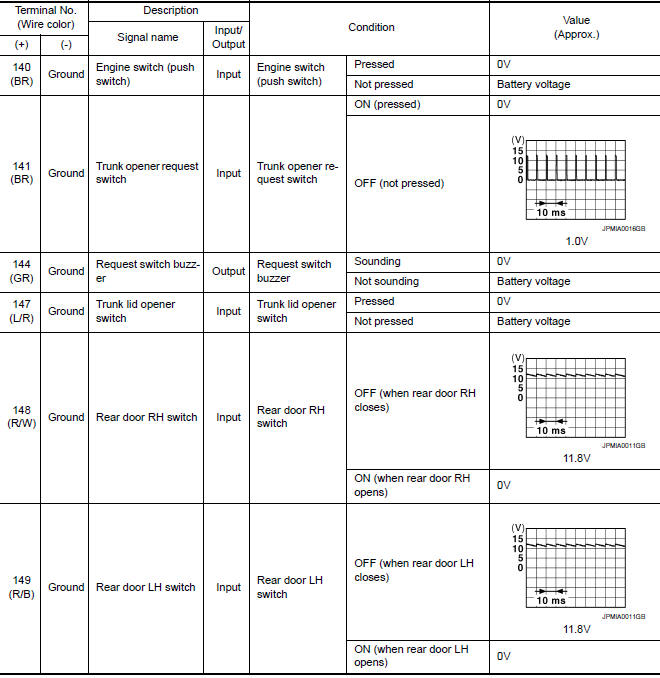
Reference Value
NOTE: The Signal Tech II Tool (J-50190) can be used to perform the following functions. Refer to the Signal Tech II User Guide for additional information.
- Activate and display TPMS transmitter IDs
- Display tire pressure reported by the TPMS transmitter
- Read TPMS DTCs
- Register TPMS transmitter IDs
- Check Intelligent Key relative signal strength
- Confirm vehicle Intelligent Key antenna signal strength
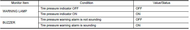
VALUES ON THE DIAGNOSIS TOOL
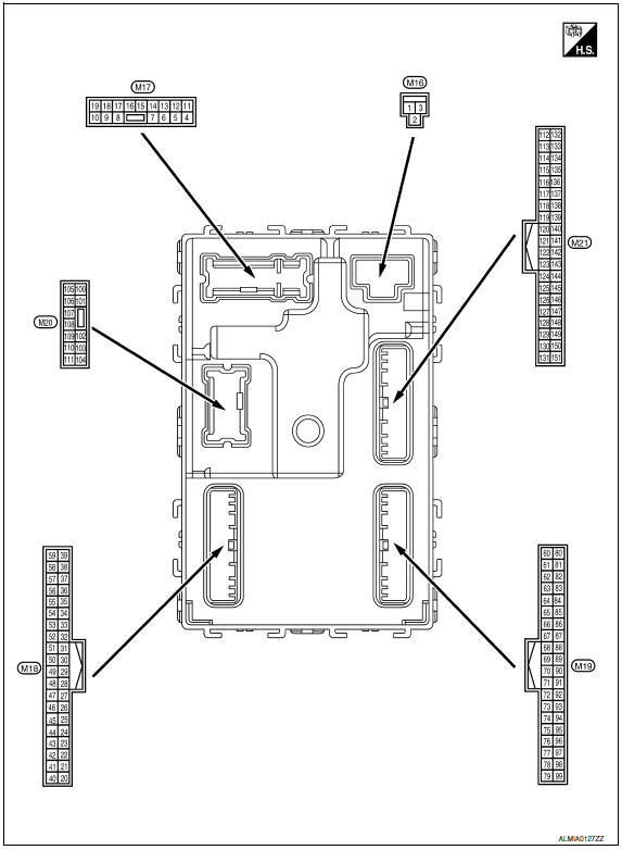
Terminal Layout
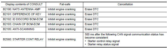
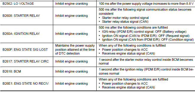
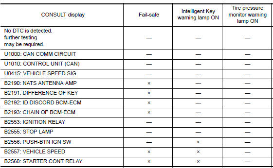
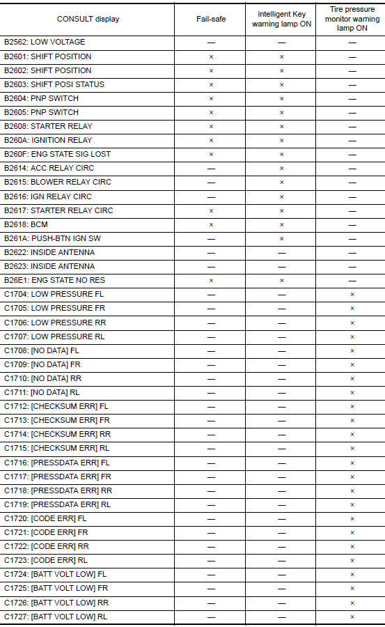
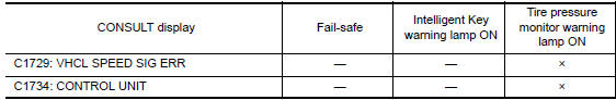
Fail Safe
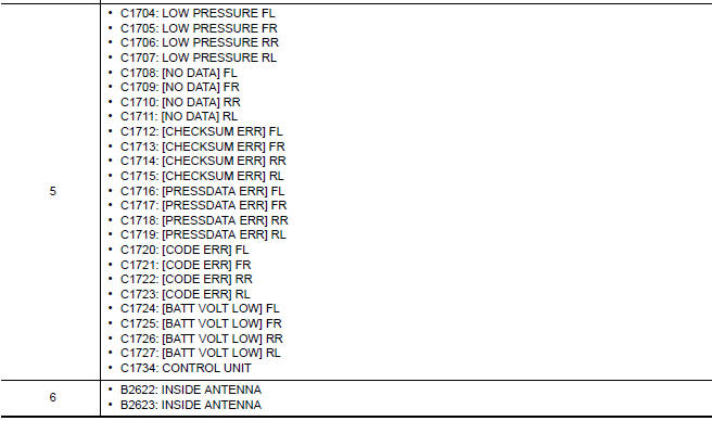
DTC Inspection Priority Chart
If some DTCs are displayed at the same time, perform inspections one by one based on the following priority chart.
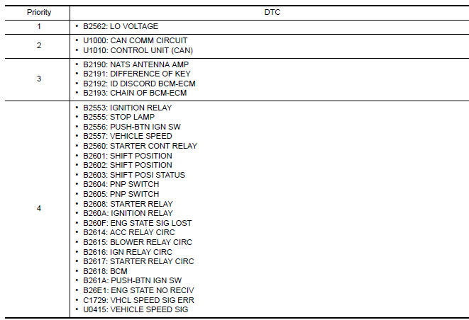
DTC Index
NOTE: Details of time display
- CRNT: Displays when there is a malfunction now or after returning to the normal condition until turning ignition switch OFF → ON again.
- 1 - 39: Displayed if any previous malfunction is present when current condition is normal. It increases 1 → 2 → 3...38 → 39 after returning to the normal condition whenever ignition switch OFF → ON. The counter remains at 39 even if the number of cycles exceeds it. It is counted from 1 again when turning ignition switch OFF → ON after returning to the normal condition if the malfunction is detected again.
 Automatic drive positioner control unit
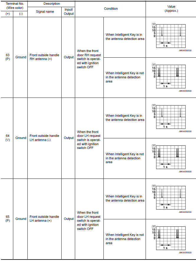
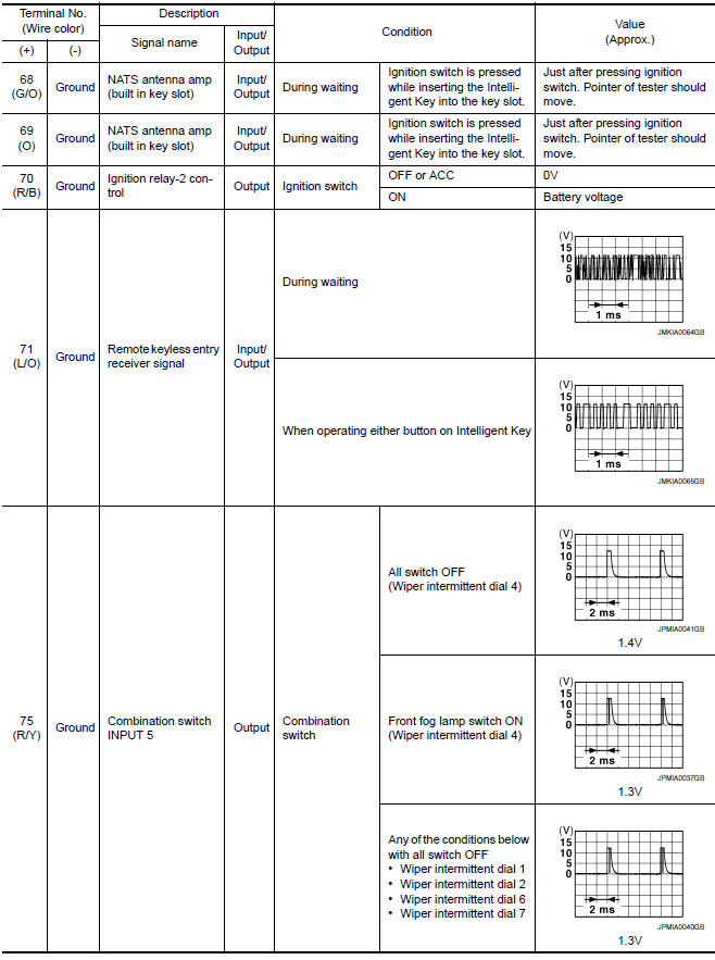
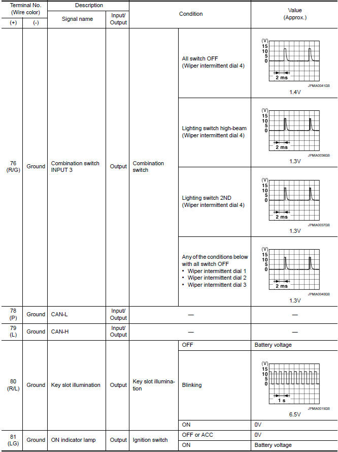
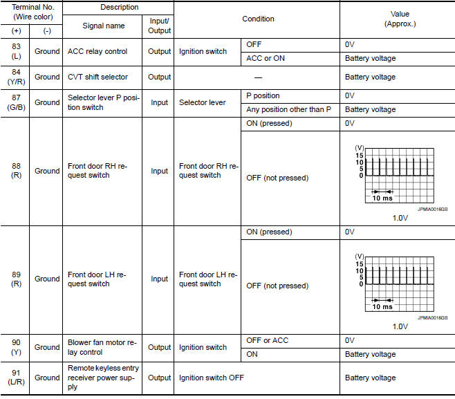
Reference Value
TERMINAL LAYOUT
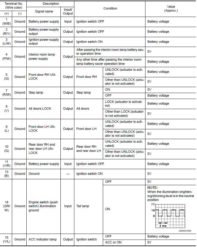
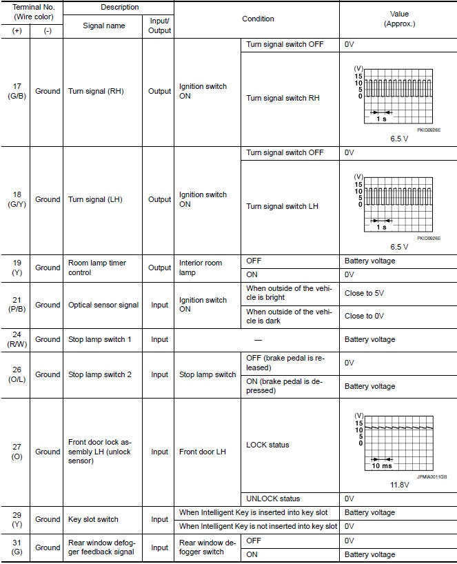
PHYSICAL VALUES
...
 Wiring diagram
AUTOMATIC DRIVE POSITIONER
Wiring Diagram
...
Other materials:
Key slot
Diagnosis Procedure
Regarding Wiring Diagram information, refer to SEC-147,
"Wiring Diagram" or SEC-128, "Wiring Diagram".
1.CHECK KEY SLOT POWER SUPPLY CIRCUIT
Turn ignition switch OFF.
Disconnect key slot connector.
Check voltage between slot harness co ...
Periodic maintenance
FOR USA AND CANADA
FOR USA AND CANADA : Introduction of Periodic Maintenance
The following tables show the normal maintenance schedule. Depending upon
weather and atmospheric conditions,
varying road surfaces, individual driving habits and vehicle usage, additional
or more frequent maintenan ...
Towing your vehicle
When towing your vehicle, all State (Provincial in
Canada) and local regulations for towing must be
followed. Incorrect towing equipment could damage
your vehicle. Towing instructions are available
from a NISSAN dealer. Local service operators
are generally familiar with the applicable laws
an ...
Nissan Maxima Owners Manual
- Illustrated table of contents
- Safety-Seats, seat belts and supplemental restraint system
- Instruments and controls
- Pre-driving checks and adjustments
- Monitor, climate, audio, phone and voice recognition systems
- Starting and driving
- In case of emergency
- Appearance and care
- Do-it-yourself
- Maintenance and schedules
- Technical and consumer information
Nissan Maxima Service and Repair Manual

0.0065