Nissan Maxima Service and Repair Manual: Wiring diagram
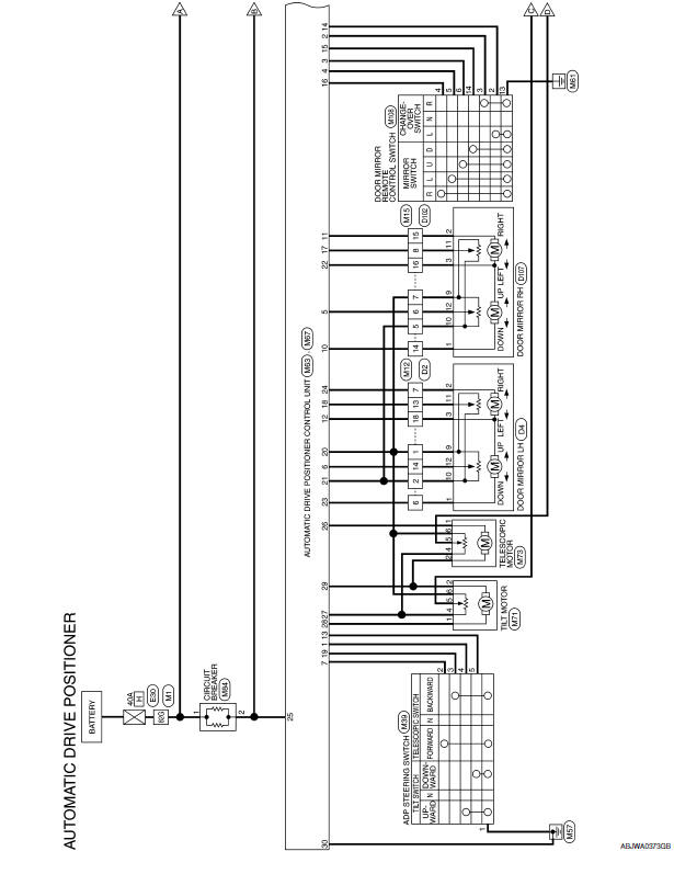
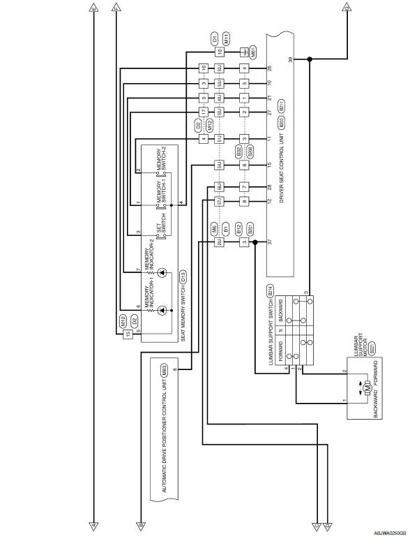
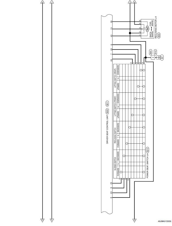
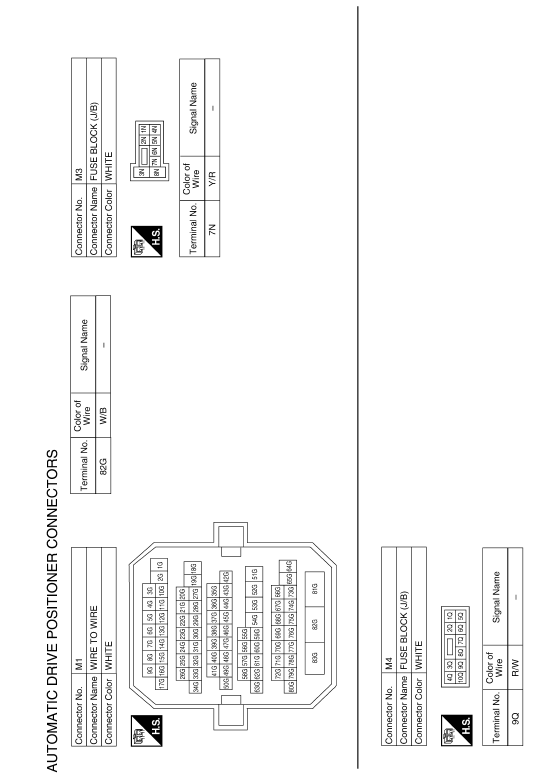
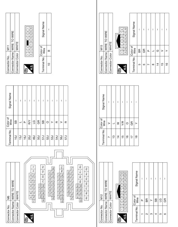
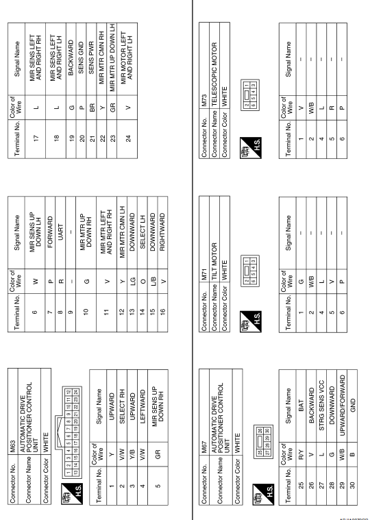
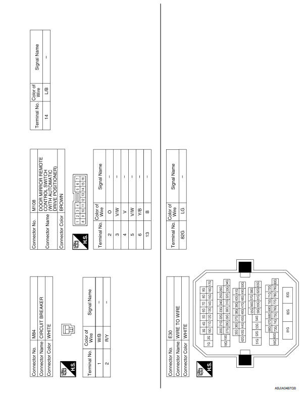
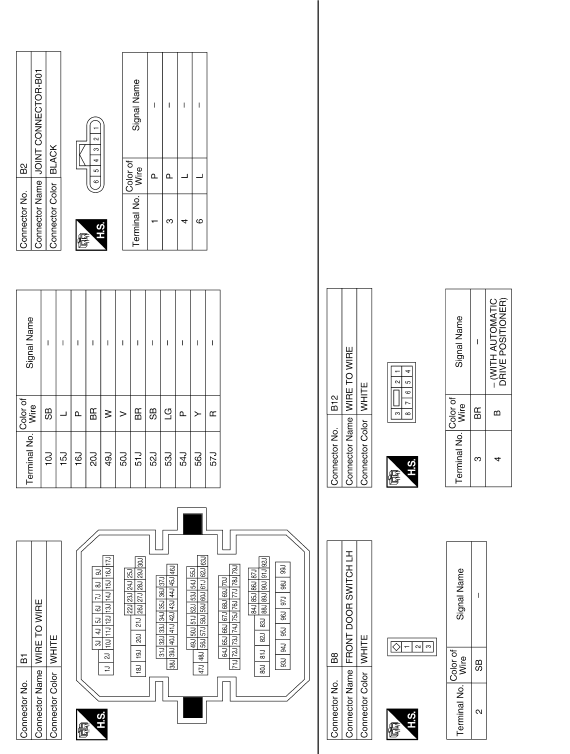
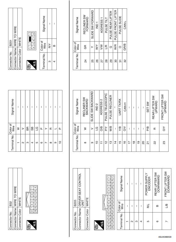
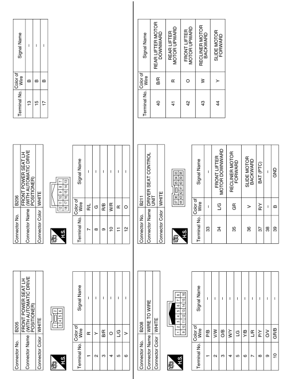
AUTOMATIC DRIVE POSITIONER
Wiring Diagram
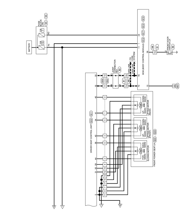
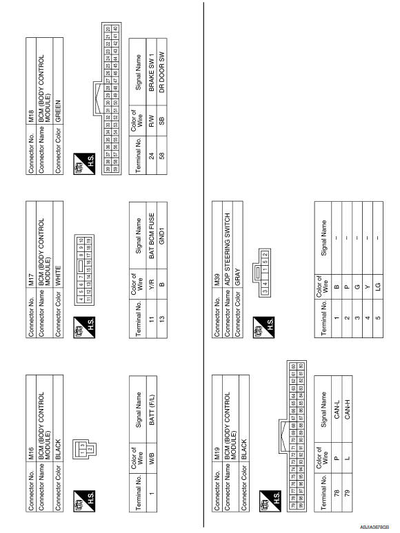
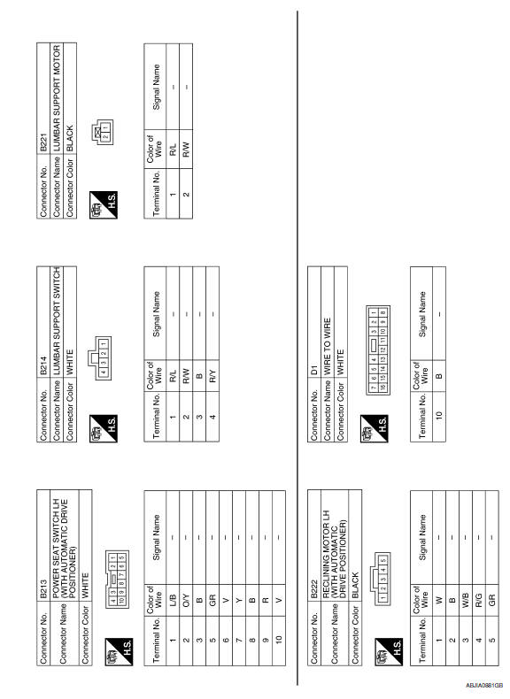
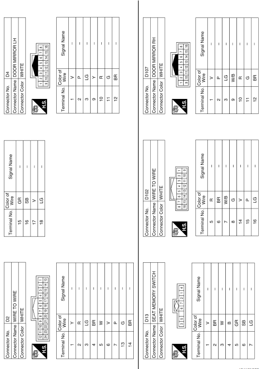
 BCM (body control module)
Reference Value
NOTE: The Signal Tech II Tool (J-50190) can be used
to perform the following functions. Refer to the Signal Tech II User Guide
for additional information.
Activate and display ...
 Symptom diagnosis
ADP SYSTEM SYMPTOMS
Symptom Table
SYMPTOM 1
SYMPTOM 2
SYMPTOM 3
SYMPTOM 4
SYMPTOM 5
NORMAL OPERATING CONDITION
Description
The following symptoms are normal operations, and they do ...
Other materials:
Diagnosis system (audio unit)
Diagnosis Description
Self-diagnosis mode can perform the following items.
Versions display
Channel check diagnosis
Key check diagnosis
AV communication diagnosis
VERSIONS DISPLAY FUNCTION
Turn ignition switch ON.
Turn the audio unit off.
While pressing "1" button, turn vol ...
Fuel injector
Description
The fuel injector is a small, precise solenoid valve. When the ECM
supplies a ground to the fuel injector circuit, the coil in the fuel injector
is energized. The energized coil pulls the ball valve back and
allows fuel to flow via the fuel injector into the intake manifold. T ...
Unlocking doors
1. Press the button on the
Intelligent
Key.
2. The driver's door will unlock and the hazard
warning lights flash once, and the front and
tail lights will turn on for 30 seconds.
3. Press the button again
within one
minute, the outside buzzer sounds once and
the remai ...
Nissan Maxima Owners Manual
- Illustrated table of contents
- Safety-Seats, seat belts and supplemental restraint system
- Instruments and controls
- Pre-driving checks and adjustments
- Monitor, climate, audio, phone and voice recognition systems
- Starting and driving
- In case of emergency
- Appearance and care
- Do-it-yourself
- Maintenance and schedules
- Technical and consumer information
Nissan Maxima Service and Repair Manual

0.0051